
Britain 624*
A.D. 1878 № 624*.
Revolving Cylinder Pistols.
LAKE’S DISCLAIMER AND MEMORANDUM OF ALTERATION.
Filed 6th May 1880.
In the matter of Letters Patent granted to William Robert Lake, of the Firm of Haseltine, Lake, & Co., Patent Agents, Southampton Buildings, London, for the Invention of “Improvements in Revolving Cylinder Pistols.” A communication from abroad by Owen Jones, of Philadelphia, Pennsylvania, United States of America. Dated the 14th February 1878, No. 624.
DISCLAIMER AND MEMORANDUM OF ALTERATION proposed to be entered by the said William Robert Lake.
WHEREAS Her most Gracious Majesty Queen Victoria, by Her Letters Patent bearing date the 14th day of February, in the year of our Lord, One thousand eight hundred and seventy eight, in the forty first year of Her reign, did, for Herself, Her heirs and successors, give and grant unto unto me, the said William Robert Lake, my executors, administrators, and assigns, the sole privilege of making, using, exercising, and vending, within the United Kingdom of Great Britain and Ireland, the Channel Islands, and Isle of Man, the said Invention for “Improvements in Revolving Cylinder Pistols.” for and during the term of fourteen years, thence next ensuing, a Complete Specification of which Invention was filed with the Petition for the said Letters Patent;
And whereas, since the filing of the said Specification, I have been advised that certain portions of the Invention set forth in the description and claiming clauses of the said Specification were not new in respect of the public knowledge and use thereof at the date of the said application, and that certain other portions of the description were ambiguous by reason of the inaccuracy of the language thereof.
NOW KNOW YE therefore that I, the said William Robert Take, by, and with the consent of Her Majesty’s Solicitor General, do alter and amend the said Specification as follows, that. is to say:— Referring to the Queen’s Printer’s copy of the said Specification, and to page 1 of the same, 1 strike out the whole of the matter contained in lines 16, 17, 18 and 19. In page 2, line 26, I strike out the words “The tool tube will now be explained.” In page 3, line 6, I strike out the word “discharge” and substitute therefor the word “eject,” and I make the same alteration in page 4, line 30. In page 3, line 41, after the letter “e” I strike out “5” and insert “3.” In page 5, lines 6 and 13, I strike out the word “discharged” and substitute therefor the word “ejected.” In page 6, lines 47 and 53, I strike out the word “discharging” and substitute therefor the word “ejecting.” In page 7, line 29, I strike out the word “discharge” and substitute therefor the word “eject.” In line 53, after the word “Figures” I strike out “1 to 6ᵃ” and substitute therefor “3 and 4,” and after the word “Drawings” I strike out the word “consisting” and insert the words “as and.” In line 54, I strike out the words “mainly of the “improved catch, and the tool tube attached to the barrel.” In page 8, line 2, I strike out after the word “Drawings” the words “as set forth in the following “clauses.” I strike out the whole of the mutter contained in lines 3, 4, 5 and 6. I strike out the word “Also,” commencing line 7, and I strike out the whole of the matter contained in and between lines 11 and 35. In line 86 [ strike out the word “Fourth” and substitute therefor the word “Third.” In line 38 I strike out the word “Fifth” and substitute therefor the word “Fourth.” In line 42, after the word “connections” I strike out the words “as above described” and insert the words ” by means of.” In line 43 I strike out the words “Also in combination “with,” and in the same line after the word “studs” I insert the word “and,” and I strike out the whole of the matter contained in lines 45 and 46, and in lines 49, 50, 51, and 42,
And in order that the effect of the said Disclaimer and Memorandum of Alteration may be fully understood, I annex a copy of the said Specification (omitting the introductory and concluding clauses thereof) as it will appear when such Disclaimer has been made.
“This Invention consists,—
“First. In certain improvements upon the pistol described in the Specification of former Letters Patent, dated 7th July A.D. 1876, No. 2777.
“Secondly. In certain modifications of the said pistol, as fully hereinafter described.
“In the accompanying Drawings,—
“Figures 1 to 6A are various views of the pistol described in the said former Specification with certain improvements applied thereto as will now be fully described.
“A, Figures 1, 2, 4, and 5 represents the stock or frame provided with the projecting ears a, a, having a transverse central opening, as shewn in Figure 4.
“B represents the catch piece proper, consisting of the transverse cylindrical pin 6 adapted to slide in the openings of the ears a, d, and the lever arm b¹ pivoted at the point b² as shewn.
“The cylindrical pin b it will be observed is provided with an inclined face b³, the purpose of which will be hereinafter explained.
“A spring of any suitable construction is employed lo return the lever arm b¹ to its normal position after it has been moved for any purpose.
“C, Figure 2, represents the lever barrel, having the strap or bar c provided at its rear end with on annular projection c¹ and a dependent wedge piece c², as shewn.
“The operation of these parts will be readily understood. When the barrel is in its normal position, as represented in Figure 1, the catch may be actuated to release the same by pushing in the thumb piece x of the lever arm b¹, by which action the cylindrical pin will be withdrawn from the opening of the projection c¹ of the lever barrel, and the latter consequently being released may be tilted on its binge.
“When the barrel has been tilted and it is desired to return the same to its normal position it may be simply swung on its pivot or hinge to its place, as the catch will act automatically to securely lock the same in its proper position.
“This automatic action is accomplished in the following manner, that is to say:—
“The cylindrical pin b, which normally is held by the pressure of the spring of the lever arm b¹ in the position shewn in Figure 3, is moved out of position to permit ; the entrance of the projection c! into its proper place between the ears a, a, of the stock A by the contact of the wedge pin c² upon the lever barrel with the inclined face b² of the pin. When, however, the projection has passed fully into its place its opening is brought into line with the cylindrical pin b, and the latter being free to act is caused to enter the same by the reaction of the pressure spring of the lever arm b¹.
“D, Figures 1 and 2, represents a tube of convenient size and length, and which is rigidly secured to the barrel block and barrel below the latter in any suitable manner. (represents a cap or cover adapted to close the open end of the tube, which may be removably secured to the latter by means of a screw thread or bayonet joint as may be preferred. d¹, Figure 2ᵃ, represents a recess in the cap adapted to secure either end of the screwdriver blade d³, hereinafter described.
“When the parts are united, as shewn in Figure 2ᵃ, the cap serves as a proper handle for the blade.
“d² Figures 2, 6, and 6ᵃ, represents a wiping rod, consisting of independent sections of suitable length to lie in the tube, which are readily united for use “when desired by screwing the same together, as shewn in Figure 6ᵃ; d³, Figures 2, 2ᵃ, and 6, represents the aforesaid screw driver blade, each end of which is adapted for use, one end being suitable for smaller screws and the other for larger screws, as shewn.
“Certain minor details of construction will now be described.
“a¹, Figure 4, represents a friction roller which may be located upon the pin a², Figures 3 and 4, of the lever barrel for the purpose of reducing the friction of its movement in the slot of the cylinder link a³.
“a⁴, Figures 3 and 4, represents a removable stop pin held at its ends in openings in the lever arm, and which extends through a recess a⁵ of the frame and serves to arrest the tilting movement of the lever barrel at the proper point, this result being accomplished at the proper time by the contact of the pin with the wall of the recess. By the simple removal of this pin a further movement of the lever barrel is permitted, in consequence of which the cylinder may be removed from the centre pin if desired.
“Figures 7, 8, 9, 10, 11, 12, 13, and 14, are various views of one modification of this Invention, which will now be described.
“The said Invention as here shown consists mainly in the combination of certain independent mechanism for extracting the cartridge shells, with independent mechanism for changing the shape or position of a portion of the cartridge shell to bring it within the range of the extracting mechanism. It consists further in certain details of construction which in connection with the foregoing will be fully hereinafter described.
“In these Figures of the Drawings,—
“Figure 7 represents a partial sectional elevation of the loaded pistol with one of the cartridges exploded.
“Figure 8 is a similar view with the cylinder moved into position to eject the cartridge.
“Figure 9 is a view of the said cylinder detached, with the cartridges in place.
“Figures 10 and 11 illustrate the relative positions in the cylinder of the cartridges, and the extracting mechanism.
“Figure 12 is a partial view of the loaded cylinder.
“And Figures 13 and 14 are views of the extracting sleeve and centre pin,
“The cartridges having been first arranged in the cylinder in such manner as to be entirely independent of the extractor, but in close proximity thereto, are then successively exploded in the usual manner by the impact of the hammer. By this impact also a portion of the cartridge shell is forced out of its normal shape or position and caused to engage with the extractor, so that when the proper devices are actuated it may be thrown out in the usual manner.
” E, Figures 7 and 8, represents the frame of the pistol, and e, the barrel, which may he constructed in any suitable manner.
“e¹, Figures 7 and 14, represents a centre pin projecting forward from the frame, and which is screwed into place in the usual manner, and is provided with the head e² as shewn.
“e³, Figures 7 and 13, represents a sleeve located on the pin between the head e² and the frame and which is adapted to turn freely thereon. It is provided at its extreme rear end with a ratchet face e¹, Figure 13ᵃ, and adjacent thereto with an annular flange or shoulder e⁵ and an annular groove or recess e⁶ as shewn.
“e⁷, Figures 8 and 13, represents a stud or projection near its front end, by means of which rigid connection is made with the cylinder, as far as revolution is concerned, without affecting the freedom of its longitudinal movement.
“e⁸, Figures 8, 11, and 12, represents the cylinder constructed in the usual well known or other proper manner, but provided with a longitudinal groove or recess e⁹ and an annular recess e¹⁰ at, its rear end.
“e¹¹ Figure 8, represents the hammer, which is constructed generally in the usual manner and operated in the ordinary way, but which is provided with an exploding point e¹², shown in dotted lines, so arranged as to strike when released by the trigger behind the shoulder of the extractor sleeve down into the recess. e¹³ represents the cartridge shall, which may be of the usual well-known construction, but which is preferably constructed as hereinafter described.
“When the parts are in their proper position the cartridges e¹⁵ and the extracting device e³ are independently held in the cylinder, the former not being either in contact with the latter or within the line of its action, because the annular flange e⁵ of the latter occupies a central space which lies wholly within the circle wherein the cartridges are located, as shewn. The upper cartridge x however is in contact, it will be observed, with the flange e⁵ of the extracting device, the same being represented as having been exploded. The operation will be readily understood. The pistol after having been properly loaded may be fired in the usual manner. By the descent of the hammer the cartridges are exploded, but furthermore a portion of the flange is turned over into such position as to project or extend behind the shoulder or flange e⁵ of the extractor, as represented in the cartridge x , Figure 10, and in all the cartridges, Figure 11. In consequence of this change of shape or position it follows that when the cylinder is drawn forward the shell cannot move with it because it is held by the contact of its projecting portion with the fixed shoulder of the extractor. Hence the shell may be extracted by simply drawing the cylinder away from it in the usual well-known manner. It will be observed that only the shell which is struck by the hammer will be caused to engage with the extractor, hence the loaded shells will never be disturbed under any circumstances.
“Certain forms of cartridges which may be employed in connection with the extracting mechanism are represented in Figures 15, 16, and 17, and will now be described. F represents a cartridge which may be constructed in any suitable manner, but is essentially provided with the usual annular flange f, and also with an auxiliary annular flange f¹ extending in a rearward direction, as shewn ; f² represents a swell or projection by means of which the cartridge is extended in a rearward direction for the purpose of obtaining a proper bearing against the recoil shield.
“If desired, also, the auxiliary flange of the cartridge may be made with hexagonal or polygonal sides, as shown in Figures 16 and 17, for the purpose of adapting it to present a straight instead of a curved surface to the action of the hammer head.
The cartridge may be either central or rim fire, as preferred. If, however, a central fire cartridge is employed a projection to explode the same must be added to the hammer. By means of the above described construction the cartridge is adapted for use in connection with the mechanism hereinbefore specified; the ‘ auxiliary flange, it will be understood, when in its place furnishes metal in the proper position to be acted upon by the hammer head and to be turned down into the recess of the extractor. Figures 18, 19, 20, and 21, are views of another modification of my {Invention, which will now be described.
“The said Invention, as here shewn, consists mainly, first, in the combination with a relatively fixed extractor plate, a sliding cylinder, and tilting barrel of intermediate rack mechanism, for uniting the barrel to the cylinder, and communicating the movement of the former to the latter without lost motion; and, secondly, in certain details of construction, which in connection with the foregoing ‘will be fully hereinafter described.
“In the last named Figures of the Drawings,—
“Figure 18 represents a partial sectional elevation of my Invention, with the cylinder drawn out to eject a cartridge shell, the position of the loaded cartridge being indicated in dotted lines.
“Figure 19 represents a similar view, with the cylinder loaded and ready for firing.
“Figure 20 is a view representing the position of the rack device relatively to the hinge joint of the barrel.
“And Figure 21 is a view representing the position of the segmental rack bar when thrown forward by its spring to engage with the sleeve of the cylinder.
“G, Figures 18 and 19, represents the frame of the pistol constructed in any suitable manner, and of any proper size, but provided essentially below with a bar g, to which the barrel is hinged, as shewn, and above with a locking socket g¹ of any proper construction.
H represents the centre pin rigidly secured at its rear end to the frame G; it is provided at its rear end with a recess h adapted to receive and hold the extractor plate h¹, which is free to revolve thereon, as shewn; h² represents the front end of the pin of a diameter less than that of its rear portion for purposes herein after explained.
“I represents the cylinder constructed generally in the usual well known, or other suitable manner, but provided essentially with a central recess i adapted to receive the main portion of the centre pin, and a projecting sleeve i¹ adapted to receive the front end h² of the pin, the said sleeve being provided upon its exterior surface with a series of collars or annular teeth or flanges i², as shown,
“J represents the barrel hinged in any suitable manner to the frame G, and having the locking bar j and recess j¹, as shewn.
“K represents a segmental rack bar or block pivoted within the recess j¹ by means of the pin k, as shewn; its teeth k¹ are adapted to engage with the annular teeth upon the sleeve, as shewn; k² represents a pin, by means of which the rack bar K is secured in its proper position; k³ represents a spring, by means of which the rack bar, when its pin k² is removed, and the parts are disconnected, is thrown backward, as shewn in Figure 21, into proper position to engage with the sleeve when the disconnected parts are again brought together.
“The operation of my extractor will be readily understood. The pistol having been fired, the cartridge shells may be ejected by simply unlocking the catch and tilting the barrel.
“By the movement of the barrel the said rack bar is caused to actuate the cylinder and draw it away from the relatively fixed extractor plate, and hence the shells held thereby being left unsupported fall out.
“It will be observed, as indicated in Figure 18, that the cylinder has a longitudinal movement slightly in excess of the length of the cartridge shells, and hence these are ejected with absolute certainty when the barrel is tilted. This movement of the cylinder, however, on the other hand does not equal the length of a loaded shell, as shewn, in the same Figure; hence it follows that while the spent shells may be extracted at any time with absolute certainty, the loaded shells cannot by any possibility be extracted or drawn out.
“It will be observed also, as indicated in Figure 20, that the rack bar is a segment of a circle x¹ struck from the hinge point x² as a centre, and that the lower, line a of the sleeve of the barrel cuts this circle at its highest point, in teeth of the rack bar, rigidly attached thereto by means of its pins, move in the arc of a circle, coinciding at the point of contact with the horizontal line of the sleeve’s movement, and hence they successively act upon the corresponding teeth of the sleeve, and give the latter movement in a uniform straight line without strain or without ‘lost motion.’
“It will be observed also that by means of the annular teeth or flanges of the sleeve the said cylinder is permitted freely to revolve.
“Some of the advantages of the above described construction are as follows:— The cylinder is actuated to extract the cartridges without ‘lost motion’ by ‘faction of the barrel as a lever, so that tightly jammed cartridges are easily and quickly extracted. The parts employed are few in number and simple in construction, co that the cost of manufacture is slight, and there is no special liability to derangement.
“Figures 22, 23, 24, 25, 26, 27, and 28, are views of another modification of my Invention, which will now be described.
“This part of the said Invention consists mainly,—
“First. In the combination of the lever barrel (by means of which the cylinder is actuated) with the said cylinder, the parts being directly connected without independent intermediate parts.
“Secondly. In the combination with the tilting lever barrel of a movable stop, adapted to arrest the tilting barrel at the end of its normal movement for discharging the cartridges, and also, when properly actuated, to permit further movement for the purpose of allowing the said cylinder to be removed from the centre pin.
“And, Thirdly. In the combination with the lever barrel of a catch of peculiar construction.
“It consists further in certain details of construction, which in connection with the foregoing will he fully hereinafter described,
“In the Drawings illustrating this part of my Invention,—
“Figure 22 represents a side elevation of a pistol having my improvements applied thereto, with the barrel in its closed position.
“Figure 23 is a similar view shewing the barrel open.
“Figure 24 is a similar view with the barrel tilted beyond its normal position to permit the removal of the cylinder.
“And Figures 25, 26, 27, and 28, shew details of various parts.
“The main portions of the revolver not forming part of this Invention may be constructed in a similar manner to the corresponding parts previously herein described.
“The novel features of this modification of my Invention will be described for convenience and clearness under separate heads as follows, namely:—
“First, The lever barrel and cylinder.
“Second. The lever barrel and moveable stop.
“Third. The lever barrel and catch.
“First. The lever barrel and cylinder. L, Figure 22, represents the lever barrel provided with the downwardly extending portion J hinged to the lower bar or strap l¹ by means of the pivot pin l², as shewn; l³, figures 23 and 24, represents a recess formed in the rear end of the barrel block, and l⁴, l⁴,, Figures 22 and 27, studs or pins projecting from the wall or side, as shewn. These studs may either form a solid portion of the barrel block, or may consist of screws inserted from the outside, as shewn; the latter construction is preferred, because the screws before insertion can be case-hardened to make them more durable under wear. When inserted in place, however, they form practically a solid portion of the barrel.
“M, Figures 23 and 24, represents the centre pin rigidly secured at its rear end to the frame; N represents the cylinder constructed in any suitable manner, but essentially provided in front with an extended hollow sleeve n, having a single annular groove or recess n¹, as shown.
“The cylinder and lever barrel properly united are represented in Figure 22.
“Union of the parts is effected it will be observed by the studs l⁴ of the barrel and the sleeve n of the cylinder, the former resting in the annular groove of the latter, as shown. By means of this construction the parts are so united that the cylinder is compelled to move in a longitudinal direction with the barrel when the latter is tilted, but is free to revolve upon its centre pin without interference.
“The connection is such also that the necessary play incidental to the union of two parts moving in different lines is obtained in a simple manner, the studs l⁴, l⁴, rising and falling as the barrel is tilted in the annular groove of the horizontally moving cylinder to describe the are of a circle struck from the pivot pin l² as a centre. The advantages of this special construction will be readily understood.
“The barrel and cylinder are attached directly together without intermediate auxiliary connecting devices, in consequence of which the number of parts is reduced and the arm much simplified and improved.
“Secondly. The lever barrel and moveable stop l⁵, Figures 25 and 24, represents a stop projection formed upon the part l of the barrel; O represents a moveable stop consisting of a transverse plate o, Figures 22 and 23, extending beyond the solid portion of the lower bar or strap l¹ and partially over the hinge, as shewn, and a longitudinal lever arm o¹ lying in a proper recess of the bar, the latter being secured in place by a pivot pin o², as shewn; o³ represents an extended portion of the cylinder bolt spring by means of which the stop plate is ordinarily held in its normal position, as shewn in Figures 22 and 23.
“The operation of this mechanism is as follows:— When the lever arm o¹ of the stop O is not moved, and the plate o consequently remains in its normal position, the lever barrel when tilted will be arrested at the end of its normal movement for ejecting the cartridge shells by the contact of its stop projection l³ with the plate o, as shewn in Figure 23, When the parts are in this position the cylinder is securely held upon the centre pin and cannot be removed. When however the lever arm o¹ is properly actuated the plate o will be thrown outward beyond the line of movement of the stop projection l³ of the part l of the barrel, as shewn in Figure 24; hence when the barrel is tilted the projection will not engage with the plate at the end of its normal movement for ejecting the cartridge ‘ shells. The stop plate is thus made inoperative for the time being, and hence the tilting movement of the barrel may be continued until the studs l⁴, l⁴ move out of the annular groove of the cylinder and release the same, so that it may be . removed from the centre pin. The cylinder is readily placed when desired by gliding the same upon the centre pin, and tilting the barrel in such manner as to cause its studs to engage with the groove of the sleeve n.
“The advantages of this construction will be readily understood. The cylinder is positively held against accidental displacement, and yet is removed with great facility when desired.
Thirdly. The lever barrel and catch. p, p¹, Figures 23 and 25, represent ears projecting upward from the side plates of the frame, each being provided with a slot p², p³, as shewn.
“P represents a catch piece consisting of a transverse bar p⁴ having at one end a pivot opening p⁵, and at the other an angular thumb-piece p6,as shewn. This catch piece is represented in position in Figure 24. One end, it will be observed, is pivoted in the slot p2, while the other end extends through the elongated slot p3, as shown.
“The thumb-piece is curved upon its inner side to correspond with the curvature of the recess p⁷ in which it moves.
“p⁸ represents a spring of any proper construction, by means of which the catch-piece after being actuated is returned to its normal position; Q, Figures 23 and 26, represents a projecting portion of the inner end of the barrel, extending rearward in a horizontal direction, and which is provided with the horizontal recess q adapted to receive the transverse bar of the catch-piece, as shown; R represents a projecting portion extending downward at an angle in such a manner as to form an inclined plane r terminating above at the recess q, as shewn; r¹ represents an opening extending from front to rear through the portion R, which is adapted to receive the hammer head when the latter is in position to explode the cartridge, as shewn in dotted lines, Figure 22.
“The operation of this mechanism will be readily understood. When the lever barrel after having been tilted to eject the cartridges or for other purpose is retilted to return it to its normal locked position, o the inclined face of its projection R will come in contact with the pivoted catch p⁴, as shewn in dotted lines, Figure 23, and turn the same on its pivot out of the line of the projection’s movement, so that proper space is afforded for its passage. When the proper point is reached however the horizontal recess g will be opposite the transverse catch-piece p⁴, and the latter having been released by the passage beyond it of the projection R will be moved into the same by the re-action of the spring p⁸, and thus act to securely lock the barre) in place. The opening r¹ in the projection R is so arranged relatively to the hammer head that the latter when in position to explode the cartridge bears against its lowest edge, as shewn in dotted lines in Figure 22. By reason of this construction and arrangement it follows that the cartridge cannot be exploded unless the projection R, and consequently the barrel attached thereto, are in the proper locked position. If how-ever the said barrel is nearly, but not entirely closed, the same will be brought to its locked position by the descent of the hammer before the explosion takes place, the inclined face of the latter acting upon the projection Q to force it down into its proper place.
“The catch is exceedingly simple in its construction and operation, and yet possesses great strength. It extends entirely across the projection of the barrel, and is strongly held at each end against strain. The cartridges cannot be exploded by the hammer head unless the barre! is in its locked position,
“Having thus fully described the said Invention as communicated to me by my foreign correspondent and the manner of performing the same, I wish it understood that I claim,—
First. The improvements illustrated in Figures 3 and 4 of the Drawings, as and for the purposes specified.
“Second. The improvements illustrated in Figures 7, 8, 9, 10, 11, 12, 13, and 14, of the Drawings, that is to say:—
“The combination of the following elements, namely, an independent extractor, a cylinder as described, adapted to hold the cartridges out of the line of action of the extractor and mechanism, as described, adapted to act on the rim of the shell, and cause it to engage with the said extractor.
“Third. The improvements shewn in Figures 18, 19, 20, and 21 of the Drawings, and as set forth in the description of these Figures,
Fourth. The improvements illustrated in Figures 22, 23, 24, 25, 26, 27, and 28, of the Drawings, and consisting in the following devices or contrivances, that is to say:—
“The combination of the lever barrel with the cylinder without intermediate connections by means of the lever barrel having the studs, and the cylinder ; having the annular groove, as above described.
“Also, in combination with a tilting lever barrel, a moveable stop, as above described.
“Also, in combination with the recessed arm of the lever barrel, the pivoted catch-piece extending across the arm, and held at each of its ends, as above described.
“Also, in combination with the recessed arm and catch-piece, the projection and hammer head, as above described.”
In witness whereof, I, the said William Robert Lake, have hereunto set my hand and seal, this Twenty fifth day of March, in the year of our Lord One thousand eight hundred and eighty,
Wᴹ. ROBᵀ, LAKE (L.S)
To the Commissioners of Patents for Inventions.
I hereby grant my fiat, giving leave to the above named William Robert Lake, to file in the Great Seal Patent Office, with the Specification to which the same relates the above written Disclaimer and Memorandum of Alteration.
Hardinge S, Giffard,
Solicitor General.
Dated this 3rd day of A̶p̶r̶i̶l̶, May, 1880.
Second Edition.
A.D, 1878, 14th February, № 624,
Revolving Cylinder Pistols.
LETTERS PATENT to William Robert Lake, of the Firm of Haseltine, Lake, & Co., Patent Agents, Southampton Buildings, London, for the Invention of “Improvements in Revolving Cylinder Pistols.” A communication from abroad by Owen Jones, of Philadelphia, Pennsylvania, United States of America.
Sealed the 5th April 1878, and dated the 14th February 1873.
COMPLETE SPECIFICATION filed by the said William Robert Lake at the Office of the Commissioners of Patents on the I4th February 1878.
William Robert Lake, of the Firm of Haseltine, Jake, & Co. Patent Agents, Southampton Buildings, London. “Improvements in Revolving Cylinder Pistols.” A communication from abroad by Owen Jones, of Philadelphia, Pennsylvania, United States of America.
This Invention consists,—
First. In certain improvements upon the pistol described in the Specification of former Letters Patent, dated 7th July, A.D. 1876, No. 2777.
Secondly, In certain modifications of the said pistol, as fully herein-after described.
In the accompanying Drawings,—
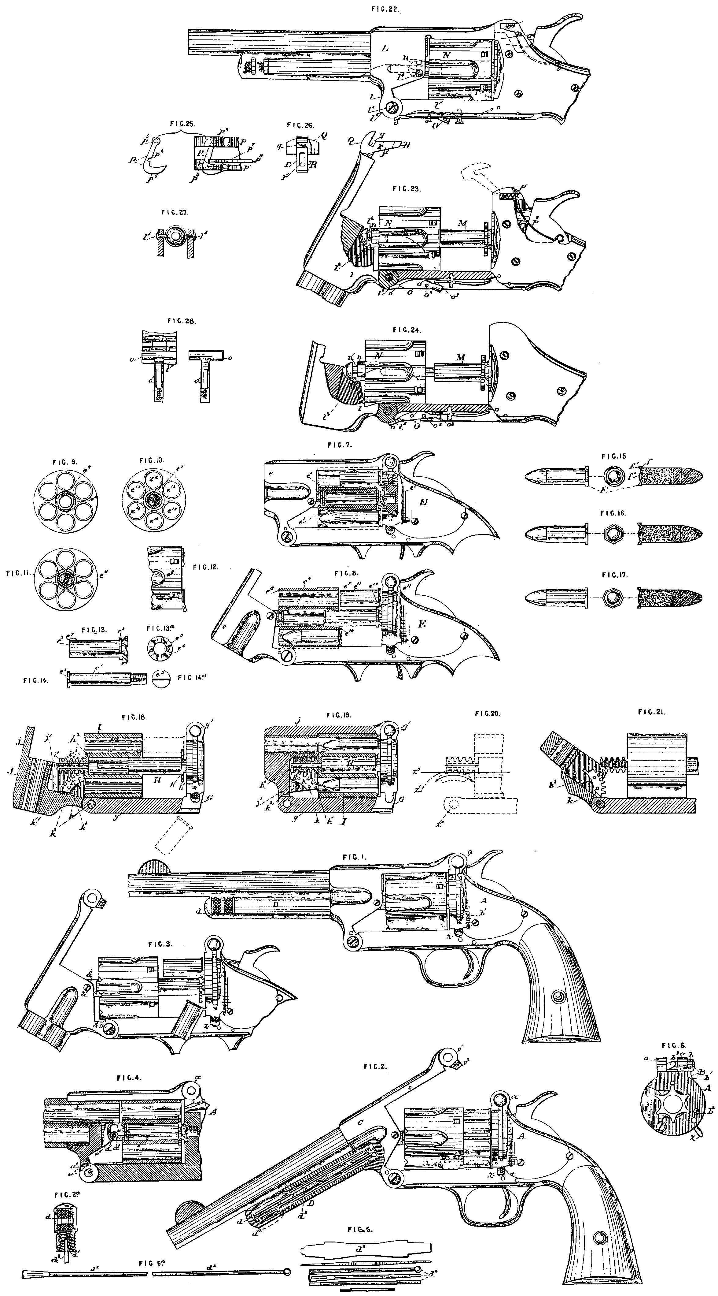
Figures 1 to 6ᵃ are various views of the pistol described in the said former Specification, with certain improvements applied thereto, as will now be fully described.
These improvements consist mainly, first, in a catch of peculiar construction for locking the !ever barrel in its normal position; and secondly, in a tube of peculiar construction which is combined with the barrel to form a receptacle for tools. This catch will now be described.
A, Figures 1, 2, 4, and 4, represents the stock or frame provided with the projecting ears a, a, having a transverse central opening, as shown in Figure 4.
B represents the catch piece proper, consisting of the transverse cylindrical pin b adapted to slide in the openings of the ears a, a, and the lever arm b¹ pivoted at the point b² as shown.
The cylindrical pin b it will be observed is provided with an inclined face b the purpose of which will be herein-after explained,
A spring of any suitable construction is employed to return the lever arm b¹ to its normal position after it has been moved for any purpose.
C, Figure 2, represents the lever barrel, having the strap or bar c provided at its rear end with an annular projection c¹ and a dependent wedge piece c², as shown.
The operation of these parts will be readily understood. When the barrel is in its normal position, as represented in Figure 1; the catch may be actuated to release the same by pushing in the thumb piece x of the lever arm b¹, by which action the cylindrical pin will be withdrawn from the opening of the projection c¹ of the lever barrel, und the latter consequently being released may be tilted on its hinge.
When the barrel has been tilted and it is desired to return the same to its normal position it may be simply swung on its pivot or hinge to its place, as the catch will act automatically to securely lock the same in its proper position.
This automatic action is accomplished in the following manner, that is to say:— The cylindrical pin b, which normally is held by the pressure of the spring of the lever arm b¹, in the position shown in Figure 5, is moved out of position to permit the entrance of the projection c¹ into its proper place between the ears a, a, of the stock A by the contact. of the wedge pin c² upon the lever barrel with the inclined face b³ of the pin. When however the projection has passed fully into its place its opening is brought into line with the cylindrical pin b, and the latter being free to act, is caused to enter the same by the reaction of the pressure spring of the lever arm b¹.
The tool tube will now be explained.
D, Figures 1 and 2, represents n tube of convenient size and length, and which is rigidly secured to the barrel block and barrel below the latter in any suitable manner. d represents a cap or cover adapted to close the open end of the tube, which may be removably secured to the latter by means of a screw thread or by o net joint, as may be preferred. d¹, Figure 2ᵃ, represents a recess in the cap adapted to secure either end of the screwdriver blade d³, herein-after described.
When the parts are united, as shown in Figure 2ᵃ, the cap serves as a proper handle for the blade.
d², Figures 2, 6,and 6ᵃ, represents a wiping rod, consisting of independent sections of suitable length to lie in the tube, which are readily united for use when desired by screwing the same together, as shown in Figure 6ᵃ. d³, Figures 2, 2ᵃ, and 6. represents (be aforesaid screwdriver blade, each end of which is adapted for use, one end being suitable for smaller screws and the other for larger screws, as shown.
Certain minor details of construction will now be described.
a¹, Figure 4, represents a friction roller which may be located upon the pin a², Figures 3 and 4, of the lever barrel for the purpose of reducing the friction of its movement in the slot of the cylinder link a³.
a¹, Figures 3 and 4, represents a removable stop pin held at its ends in openings in the lever arm, and which extends through a recess a³ of the frame, and serves to arrest the tilting movement of the lever barrel at the proper point, this result being accomplished at the proper time by the contact of the pin with the wall of the recess. By the simple removal of this pin a further movement of the lever barrel is permitted in consequence of which the cylinder may be removed from the centre pin if desired.
Figures 7, 8, 9, 10, 11, 12, 13, and 14, are various views of one Modification of this Invention, which will now be described.
The said Invention as here shown consists mainly in the combination of certain independent mechanism for extracting the cartridge shells, with independent mechanism for changing the shape or position of a portion of the cartridge shell to bring it within the range of the extracting mechanism. It consists further in certain details of construction, which in connection with the foregoing will be fully herein-after described.
In these Figures of the Drawing:,—
Figure 7 represents a partial sectional elevation of the loaded pistol with one of the cartridges exploded.
Figure 8 is a similar view with the cylinder moved into position to discharge the cartridge.
Figure 9 is a view of the said cylinder detached, with the cartridges in place.
Figures 10 and 11 illustrate the relative positions in the cylinder of the cartridges, and the extracting mechanism.
Figure 12 is a partial view of the loaded cylinder.
And Figures 13 and 14 are views of the extracting sleeve and centre pin.
The cartridges having been first arranged in the cylinder in such manner as to be entirely independent of the extractor, but in close proximity thereto, are then successively exploded in the usual manner by the impact of the hammer. By this impact also portion of the cartridge shell is forced out of its normal shape or position and caused to engage with the extractor, so that when the proper devices are actuated it may be thrown out in the usual manner.
E, Figures 7 and 8, represents the frame of the pistol, and e the barrel, which may be constructed in any suitable manner.
e¹, Figures 7 and 14, represents a centre pin projecting forward from the frame, and which is screwed into place in the usual manner,and is provided with the head e², as shown.
e³, Figures 7 and 18, represents a sleeve located on the pin between the head e² and the frame, and which is adapted to turn freely thereon. It is provided at its extreme rear end with a ratchet face e⁴, Figure 13ᵃ, and adjacent thereto with an annular flange or shoulder e⁵, and an annular groove or recess e⁶, as shewn.
e⁷, Figures 8 and 13, represents a stud or projection near its front end, by means of which rigid connection is made with the cylinder. as far as revolution is concerned, without affecting the freedom of its longitudinal movement.
e⁸, Figures 8, 11, and 12, represents the cylinder constructed in the usual well known or other proper manner, but provided with a longitudinal groove or recess e⁹, and an annular recess e¹⁰ at its rear end.
e¹¹, Figure 8, represents the hammer, which is constructed generally in the usual manner, and operated in the ordinary way, but which is provided with an exploding point e¹², shown in dotted lines, so arranged as to strike, when released by the trigger behind the shoulder of the extractor sleeve, down into the recess. e¹³ re-presents the cartridge shell, which may be of the usual well-known construction, but which is preferably constructed as herein-after described.
When the parts are in their proper position, the cartridges e¹³ and the extracting device e⁴ are independently held in the cylinder, the former not being either in contact with the latter, or within the line of its action, because the annular flange e⁵ of the latter occupies a central space, which lies wholly within the circle wherein the cartridges are located, as shown. The upper cartridge x* however is in contact, it will be observed, with the flange e⁵ of the extracting device, the same being represented as having been exploded. The operation will be readily understood. The pistol after having been properly loaded may be fired in the usual manner, By the descent of the hammer the cartridges are exploded, but furthermore a portion of the flange is turned over into such position as to project or extend behind the shoulder or flange e⁵ of the extractor, as represented in the cartridge x*, Figure 10, and in all the cartridges, Figure 11. In consequence of this change of shape or position it follows that when the cylinder is drawn forward, the shell cannot move with it because it is held by the contact of its projecting portion with the fixed shoulder of the extractor. Hence the shell may he extracted by simply drawing the cylinder away from it in the usual well-known manner. It will be observed that only the shell, which is struck by the hammer, will be caused to engage with the extractor; hence the loaded shells will never be disturbed under any circumstances,
Certain forms of cartridges, which may be employed in connection with the extracting mechanism, are represented in Figures 15, 16, and 17, and will now be described. F represents a cartridge, which may he constructed in any suitable manner, but is essentially provided with the usual annular flange f, and also with an auxiliary annular flange f¹ extending in a rearward direction, as shewn; f² represents a swell or projection, by means of which the cartridge is extended in a setae direction for the purpose of obtaining a proper bearing against the recoil shield.
If desired, also the auxiliary flange of the cartridge may be made with hexagonal or polygonal sides, as shown in Figures 16 and 17, for the purpose of adapting it to present a straight instead of curved surface to the action of the hammer head.
The cartridge may be either central or rim fire, as preferred. If, however, a central fire cartridge is employed a projection to explode the same must be added to the hammer. By means of the above-described construction the cartridge is adapted for use in connection with the mechanism herein-before specified; the auxiliary flange, it will be understood, when in its place furnishes metal in the proper position to be acted upon by the hammer head, and to be turned down into the recess of the extractor, Figures 18,19, 20, and 21 are views of another modification of my Invention, which will now be described.
The said Invention, as here shown, consists mainly, first, in the combination with a relatively fixed extractor plate, a sliding cylinder, and tilting barrel of inter-mediate rack mechanism, for uniting the barrel to the cylinder, and communicating the movement of the former to the latter without lost motion; and, secondly, in certain details of construction, which in connection with the foregoing will be fully herein-after described.
In the last-named Figures of the Drawings,—
Figure 18 represents a partial sectional elevation of my Invention, with the cylinder drawn out to discharge a cartridge shell, the position of the loaded cartridge being indicated in dotted lines.
Figure 19 represents a similar view, with the cylinder loaded and ready for firing.
Figure 20 is a view representing the position of the rack device relatively to the hinge joint of the barrel.
And, Figure 21 is a view representing the position of the segmental rack bar when thrown forward by its spring to engage with the sleeve of the cylinder.
G, Figures 18 and 19, represents the frame of the pistol constructed in any suitable manner, and of any proper size, but provided essentially below with a bar g, to which the barrel is hinged, as shown, and above with a locking socket g¹, of any proper construction.
H represents the centre pin rigidly secured at its rear end to the frame G; it is provided at its rear end with a recess h, adapted to receive and hold the extractor plate h¹, which is free to revolve thereon, as shown. h² represents the front end of the pin of a diameter less than that of its rear portion, for purposes herein-after explained.
I represents the cylinder constructed generally in the usual well known or other suitable manner, but provided essentially with a central recess i, adapted to receive the main portion of the centre pin, and a projecting sleeve i¹ adapted to receive the front end h² of the pin, the said sleeve being provided upon its exterior surface with a series of collars or annular teeth, or flanges i², as shown.
J represents the barrel hinged in any suitable manner to the frame G, and having the locking bar j and recess j¹, as shown.
K represents a segmental rack bar or block pivoted within the recess j¹ by means of the pin k, as shown; its teeth k¹ are adapted to engage with the annular teeth upon the sleeve, as shown; k² represents a pin, by means of which the rack bar K is secured in its proper position ; k³ represents a spring, by means of which the rack bar, when its pin k² is removed, and the parts are disconnected, is thrown backward as shown in Figure 21, into proper position to engage with the sleeve when the disconnected parts are again brought together.
The operation of my extractor will be readily understood. The pistol having been fired, the cartridge shells may be discharged by simply unlocking the catch and tilting the barrel.
By the movement of the barrel the said rack bar is caused to actuate the cylinder and draw it away from the relatively fixed extractor plate, and hence the shells held thereby being left unsupported fall cut.
It will be observed, as indicated in Figure 18, that the cylinder has a longitudinal movement slightly in excess of the length of the cartridge shells, and hence these are discharged with absolute certainty when the barrel is tilted. This movement of the cylinder, however, on the other hand does not equal the length of a loaded shell, as shown in the same Figure; hence, it follows that while the spent shells may be extracted at any time with absolute certainty, the loaded shells cannot by any possibility be extracted or drawn out.
It will be observed also, as indicated in Figure 20, that the rack bar is a segment of a circle x² struck from the hinge point a as a centre, and that the lower line x³ of the sleeve of the barrel cuts this circle at its highest point, in consequence of which it follows that when the barrel is tilted on its hinge, the teeth of the rack bar rigidly attached thereto by means of its pins, move in the are of a circle, coinciding at the point of contact. with the horizontal line of the sleeve’s movement, and hence they successively act upon the corresponding teeth of the sleeve, and
give the latter movement in a uniform straight line without strain or without “lost motion.”
It will be observed, also, that by means of the annular teeth or flanges of the sleeve the said cylinder is permitted freely to revolve.
Some of the advantages of the above-described construction are as follows:— The cylinder is actuated to extract the cartridge without “lost motion” by action of the barrel ag a lever, so that tightly jammed cartridges are easily and quickly extracted. The parts employed are few in number and simple in construction, so that the cost of manufacture is slight and there is no special liability to derangement.
Figures 22, 23, 24, 23, 26, 27, and 28 are views of another modification of my Invention which will now be described.
This part of the said Invention consists mainly,—
First. In the combination of the lever barrel (by means of which the cylinder is actuated) with the said cylinder, the parts being directly connected without independent intermediate parts.
Secondly. In the combination with the tilting lever barrel of a moveable stop, adapted to arrest the tilting barrel at the end of its normal movement for dis-charging the cartridges, and also, when properly actuated, to permit further movement for the purpose of allowing the said cylinder to be removed from the centre pin.
And, Thirdly. In the combination with the lever barrel of a catch of peculiar construction.
It consists, further, in certain details of construction, which in connection with the foregoing will be fully herein-after described.
In the Drawings illustrating this part of my Invention,—
Figure 22 represents a side elevation of a pistol having my improvements applied thereto, with the barrel in its closed position.
Figure 23 is a similar view, showing the barrel open.
Figure 24 is a similar view, with the barrel tilted beyond its normal position to permit the removal of the cylinder.
And Figures 25, 26, 27, and 28 shew details of various parts.
The main portions of the revolver not forming part of this invention may be constructed in a similar manner to the corresponding parts previously herein described.
The novel features of this modification of my Invention will be described for convenience and clearness under separate heads as follows, namely:—
First. The lever barrel and cylinder.
Second. The lever barrel and moveable stop.
Third. The lever barrel and catch.
First, The lever barrel and cylinder L, Figure 22, represents the lever barre] provided with the downwardly extending portion l, hinged to the lower bar or strap i¹ by means of the pivot pin l², as shewn; l³, Figures 22 and 24, represents a recess formed in the rear end of the barrel block, and l⁴, l⁴, Figures 22 and 27, studs or pins projecting from the wall or side, as shown. These studs may either form a solid portion of the barrel block, or may consist of screws inserted from the outside, as shown. The latter construction is preferred, because the screws before insertion can be case-hardened to make them more durable under wear. When inserted in place, however, they form practically a solid portion of the barrel.
M, Figures 23 and 24, represents the centre pin rigidly secured at its rear end to the frame; N represents the cylinder, constructed in any suitable manner, but essentially provided in front with an extended hollow sleeve n, having a single annular groove or recess n¹, as shown.
The cylinder and lever barrel, properly united, are represented in Figure 22.
Union of the parts is effected, it will be observed, by the studs l⁴ of the barrel and the sleeve n of the cylinder, the former resting in the annular groove of the latter,as shown. By means of this construction the parts are so united that the cylinder is compelled to move in a longitudinal direction with the barrel when the latter is tilted, but is free to revolve upon its centre pin without interference.
The connection is such also that the necessary play incidental to the union of two parts moving in different lines is obtained in a simple manner, the studs l⁴, l⁴, rising and falling as the barrel is tilted in the annular groove of the horizontally moving cylinder to describe the are of a circle struck from the pivot pin l² as a centre. The advantages of this special construction will be readily understood.
The barrel and cylinder are attached directly together without intermediate auxiliary connecting devices, in consequence of which the number of parts is reduced, and the arm much simplified and improved.
Secondly. The lever, barre], and moveable stop l⁵, Figures 23 and 24, represents a stop projection formed upon the part l of the barrel. O represents a moveable stop, consisting of a transverse plate o, Figures 22 and 23, extending beyond the solid portion of the lower bar or strap l¹, and partially over the hinge, as shown; and a longitudinal lever arm o¹ lying in a proper recess of the bar, the latter being secured in place by a pivot pin o², as shown. o³ represents an extended portion of the cylinder bolt spring, by means of which the stop plate is ordinarily held in its normal position, as shown in Figures 22 and 23.
The operation of this mechanism is as follows:— When the lever arm o¹ of the stop O is not moved, and the plate o consequently remains in its normal position, the lever barrel when tilted will be arrested at the end of its normal movement for discharging the cartridge shells by the contact of its stop projection l⁵ with the plate o, as shown in Figure 23. When the parts are in this position the cylinder is securely held upon the centre pin, and cannot be removed. When however the lever arm o¹ is properly actuated the plate o will be thrown outward beyond the line of movement of the stop projection {* of the part 2 of the barrel, as shewn in Figure 24; hence when the barrel is tilted the projection will not engage with the plate at the end of its normal movement for discharging the cartridge shells. The stop plate is thus made inoperative for the time being, and hence the tilting movement of the barrel may be continued until the studs l⁴, l⁴, move out of annular groove of the cylinder, and release the same, so that it may be removed from the centre pin, The cylinder is readily placed, when desired, by sliding the same upon the centre pin, and tilting the barrel in such manner as to cause its studs to engage with the groove of the sleeve n.
The advantages of this construction will be readily understood. The cylinder is positively held against accidental displacement, and yet is removed with great facility when desired. Thirdly. The lever, barrel, and catch p, p¹, Figures 23 and 25, represent ears projecting upward from the side plates of the frame, each being provided with a slot p², p³, as shown.
P represents a catch piece consisting of a transverse bar p⁴, having at one end a pivot opening p⁵, and at the other an angular thumb-piece p⁶, as shown, This catch piece is represented in position in Figure 25. One end, it will be observed, is pivoted in the slot p², while the other end extends through the elongated slot p², as shown.
The thumb-piece is curved upon its inner side to correspond with the curvature of the recess p⁷, in which it moves.
p⁸ represents a spring of any proper construction, by means of which the catch-piece, after being actuated, is returned to its normal position. Q, Figures 23 and 26, represents a projecting portion of the inner end of the barrel, extending rearward in a horizontal direction, and which is provided with the horizontal recess q adapted to receive the transverse bar of the catch-piece, as shown. R represents a projecting portion extending downward at an angle in such a manner as to form an inclined plane e, terminating above at the recess g, as shown. r¹ represents an opening extending from front to rear through the portion R, which is adapted to receive the hammer head when the latter is in position to explode the cartridge, as shown in dotted lines, Figure 22.
The operation of this mechanism will be readily understood. When the lever barrel, after having been tilted to discharge the cartridges, or for other purpose, is re-tilted to return it to its normal locked position, the inclined face of its projection R will come in contact with the pivoted catch p⁴, as shewn in dotted lines, Figure 23, and turn the same on its pivot out of the line of the projection’s movement, so that proper space is afforded for its passage. When the proper point is reached however the horizontal recess q will be opposite the transverse catch-piece p⁴, and the latter having been released by the passage beyond it of the projection R will be moved into the same by the re-action of the spring p⁸, and thus act to securely lock the barrel in place. The opening r! in the projection BR is so arranged relatively to the hammer head that the latter when in position to explode the cartridge bears against its lowest edge, as shewn in dotted lines in Figure 22. By reason of this construction and arrangement it follows that the cartridge cannot be exploded unless the projection R, and consequently the barrel attached thereto, are in the proper locked position. If however the said barrel is nearly but not entirely closed, the same will be brought to its locked position by the descent of the hammer before the explosion takes place, the inclined face of the latter acting upon the projection Q to force it down into its proper place.
The catch is exceedingly simple in its construction and operation, and yet possesses great strength. It extends entirely across the projection of the barrel. and is strongly held at each end against strain. The cartridges cannot be exploded by the hammer head unless the barrel is in its locked position.
Having thus fully described the said Invention as communicated to me by my foreign correspondent, and the manner of performing the same, I wish it understood that I claim,—
First. The improvements illustrated in Figures 1 to 6ᵃ of the Drawings, consisting mainly of the improved catch and the tool tube attached to the barrel, for the purposes specified.
Second. The improvements illustrated in Figures 7, 8, 9, 10, 11, 12, 13, and 14 of the Drawings, as set forth in the following clauses, that is to say:—
The combination of the following elements, namely, independent mechanism, as described, for extracting the cartridge shells, and independent mechanism, as described, for changing the shape or position of a portion of the cartridge shell to bring it within the range of action of the extracting mechanism.
Also, the combination of the following elements, namely, an independent extractor, a cylinder, as described, adapted to hold the cartridges out of the line of action of the extractor, and mechanism, as described, adapted to act on the rim of the shell, and cause it to engage with the said extractor.
Also, in combination with the cylinder, the extractor and the hammer, as above described.
Also, in combination with the cylinder and its centre pin, the extractor sleeve or equivalent device, and the hammer adapted to change the shape of the cartridge shell, as above described.
Also, an independent extractor lying out of the plane of the cartridges, and having a recess adapted to receive the projecting portion of a shell after the form of the shell has been changed, as above set forth.
Also, in combination with an extractor lying out of the plane of the cartridges, and having a recess, a hammer head adapted to enter the said recess, as above specified and for the purpose set forth.
Also, the contrivance or means for extracting cartridge shells, consisting essentially, first, in locating a series of cartridges in the cylinder in a circle concentric with a ventral extracting device, but out of the line of the extractor’s action; second, in changing the shape or position of the rims of two or more cartridges when the latter are exploded ty bring them within the range of the extractor’s action; and, third, in actuating the extracting device to simultaneously remove all the exploded cartridges.
Also, the combination of the following elements, namely, a cylinder adapted to hold a series of cartridges out of the line of action of the extractor, a central extractor adapted to receive the projection of all the cartridges of the series after the form of the shells has been changed, and mechanism for changing the position or form of the rims of the cartridges, all as above described.
Third. The improvements in cartridges, shown in Figures 15, 16, and 17 of the Drawings, and as set forth in the description of these Figures.
Fourth. The improvements shown in Figures 18, 19, 20, and 21 of the Drawings, and as set forth in the description of these Figures.
Fifth, The improvements illustrated in Figures 22, 23, 24, 25, 26, 27, and 28 of the Drawings, and consisting in the following devices or contrivances, that is to say :—
The combination of the lever barrel with the cylinder without intermediate connections, as above described.
Also, in combination with the lever barrel having the studs, the cylinder having the annular groove, as above described.
Also, a moveable stop adapted to permit a movement of the lever barrel beyond its normal limit, as above described.
Also, in combination with a tilting lever barrel, a movable stop, as above described.
Also, the combination of the following elements, namely, a tilting lever barrel, a removable cylinder, and a removable stop adapted to permit a movement of the; said lever barrel beyond its normal limit for the removal of the cylinder, as above described.
Also, in combination with the recessed arm of the lever barrel, the pivoted catch-piece extending across the arm, and held at each of its ends, as above described.
Also, in combination with the recessed arm and catch-piece, the projection and hammer head, as above described.
In witness whereof, I, the said William Robert Lake, have hereunto set my hand and seal, this Fourteenth day of February, in the year of our Lord One thousand eight hundred and seventy-eight.
Wᴹ, ROBᵀ. LAKE (L.S)