
US 9929
UNITED STATES PATENT OFFICE.
JOSHUA STEVENS, OF CHICOPEE, MASSACEIUSETTS, ASSIGNOR TO MASSACHUSETTS ARMS COMPANY.
IMPROVEMENT IN REPEATING FIRE-ARMS.
Specification forming part of Letters Patent No. 9,929, dated August 9, 1853.
To all whom it may concern:
Be it known that I, Joshua Stevens, of Chicopee, in the county of Hampden and State of Massachusetts, have invented certain new and useful Improvements in Repeating Fire-Arms; and I do hereby declare that the same are fully described and represented in the following specification and the accompanying drawings, letters, figures, and references thereof.
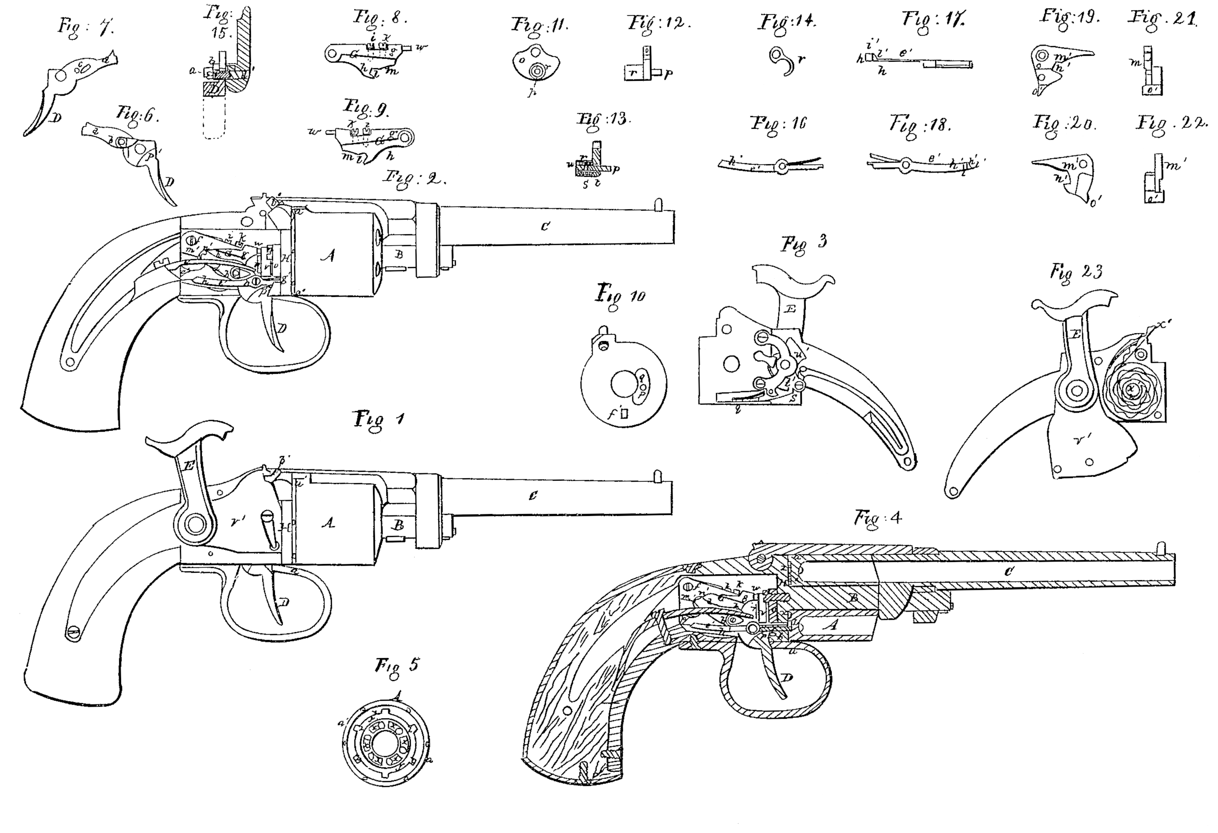
Of the said drawings, Figure 1 denotes a side view of a repeating or revolver pistol constructed in accordance with my improvements. Fig. 2 is a side view of it as it appears when the lock-plate and parts of the lock attached to such plate are removed from the stock. Fig. 3 is a view of the rear side or mechanism of the lock. Fig. 4 is a vertical central and longitudinal section of the fire-arm. Such other figures as may be necessary to a complete explanation and representation of the construction of my improved fire-arm will be hereinafter referred to and described.
In the Said drawings, A represents the rotary chambered cylinder or magazine of short barrels, which is so applied on an axle, B, as to enable a person, by turning it around, to bring each chamber of the magazine in succession in direct line with the barrel C. A view of the rear end of the cylinder A is given in Fig. 5. The said chamber is to be moved partially around during each pull of the trigger D and by mechanism directly connected with and put in operation by the trigger.
The cock of the lock is seen at E. It is not raised by the trigger when the latter is pulled backward, but is to be previously elevated by the hand or finger of a person applied directly to it. It is set free or discharged by the trigger after the latter has performed its operation of causing a rotary movement of the magazine A.
The trigger is a lever that turns on a suitable bearing, in which is inserted a screw-pin, a, arranged as seen in Fig. 2. The trigger is seen in side view in Fig. 6 and in back view in Fig. 7. A section through the trigger and its bearing d’ is given in Fig. 15. On one side of it and above its fulcrum the trigger carries a small friction-roller, b, and on the opposite side of it it has a stud or projection, c, extended from its arm d. A spring, e, whose office is to throw the arm d of the trigger downward during each forward movement of the trigger, is made to press upon the upper part of the periphery of the said roller. The stud c, when the arm d is elevated, is borne against a lever, G, that is supported by and turns at its rear end on a screw-pin, f. A view of one side of this lever is represented in Fig. 8 and of the other side in Fig. 9, wherein it is shown as composed of two pieces, g h, each of which at its rear end turns on the screw-pin f. One of these pieces—viz., the piece h— is placed under the other, and connected to it by a screw, i, that passes down through the upper piece, g, and is screwed into the piece h. Another screw, k, is screwed through and into the piece of and against the top of the piece h. On the piece h is the notch l and curve-cam m, against and with which the stud c acts in order to elevate or depress the lever G. When the arm d of the trigger is raised the stud d is borne against the curve n, and when the said arm is depressed by the reaction of the spring e the stud, entering into the notch l, depresses the lever G. The peculiar construction of the lever or its division into two parts, g h, connected and provided with screws, as described, enables a person by means of the screws to accurately adjust the curve n, so as to insure the proper degree of elevation of the lever, and this whenever the curve m or the stud which bears against it becomes worn or it may be found convenient to make any such adjustment.
The chambered cylinder or magazine has its rear end formed as represented in Fig. 5, and made to rest against a stationary breech-plate, H, that forms the front end of the lock or stock case. There is a screw-pin, n, inserted in the central part of the plate Hand within the case or stock, and made to pass through a sectoral plate, O, a side view of which is shown in Fig. 11, an end view in Fig. 12, and a section in Fig. 13. The sectoral plate turns on the screw-pin in and carries a small spring-bolt, p, that projects from its front face and passes through a curved slot, q, made through the breech-plate H, as seen in Fig. 10, which is a front view of the breech-plate. The spring-bolt p works through the sectoral plate and a cylindrical projection or box, r, extending from the rear side of the plate. This box serves to hold the helical spring s, that envelops the bolt, and has its front end resting against a collar, t, fixed on the bolt, while its rear end rests against the back of the box or a screw, u, which constitutes such back. A small stirrup, v, (a view of which is shown in Fig. 14,) is placed on the box , and turns thereon, and has a hole, w, made through it, in which hole the cylindrical end of the lever G is inserted. The outer end of the spring-bolt p operates in connection With a series of cam-notches, x x x, &c., arranged around in a circle and made in the rear end of the cylinder A, as seen in Fig. 5 of the drawings. Each cam-notch is so made that when the spring-bolt is moved upward it shall not only bear against one end of the notch and cause the magazine to revolve, but when the spring-bolt is depressed the inclination or cam of the notch shall cause the bolt to fall back and slip out of the notch and into that notch directly in rear.
Concentric with and encircling the series of cam-notches is a circular groove, y, out of whose external circumference a series of notches, z z z, are cut or formed at equal distances apart, as seen in Fig. 5.The outer edge of the rear end of the magazine is beveled off, as seen at a’. This part works against the lower end of the percussion-nipple b’, and has a series of touch-holes, c’ c’, &c., bored through it into the respective clambers of the magazine.
In the peculiar construction of the pistol shown in the drawings I employ but one percussion-nipple, and that a stationary one. The magazine may be provided with a nipple to each touch-hole, and so connected with the magazine as to be revolved or carried around with it.
The pistol represented in the drawings has the well-known “Maynard primer” adapted to it. For the convenient and correct operation of such primer I employ the single stationary percussion-nipple.
A spring-lever catch, e’, (seen in front side view in Fig. 16 and in top view in Fig. 17,) works on the screw-pin a. Its front end passes through a rectangular orifice, f’, formed through the breech-plate, and enters the groove y or one of the notches z z thereof. The said front end is borne downward into such notch by the action of a spring, g’, that is affixed to the lever and made to press against the upper end of the orifice f’. A view of the rear side of the spring-lever catch e’ is represented in Fig. 18. The rear arm, h’, of the lever-catch e’ is made to spring laterally, and is provided at its rear with a projection, i’, which has two inclined surfaces, k’, l’, that operate in connection with a bent lever, m’, that turns on the screw-pin f.
Fig. 19 denotes a front side view of the lever m’. Fig. 20 is a rear side view of it. Fig. 21 is a front edge view of it, and Fig. 22 is a rear edge view of it. The said lever m’ is formed with a recess, n’, in which the upper end of the trigger-arm d operates. When it bears against the upper part or side of the recess it elevates the lever; but when it bears against the lower side of the recess it depresses the lever. The lower end of the lever m’ is provided with a cam, o’, that during the first part of the elevation of the lever is borne against the cam or inclined surface k’ of the lever-catch e’, and so as to depress the rear arm of the lever-catch, and thereby elevate its front arm out of the notch 2, in which it may be, thus unlocking the magazine, so as to enable it to be partially rotated during the further back movement of the trigger. As soon as the can o’ is carried forward beyond the two inclined surfaces k’ l’ the spring-lever catch e is set free, so that when the next succeeding notch z comes round under its front end the reaction of the front spring, g’, will throw the catch down into the said recess z, and thus the magazine will be locked to the breech. During the back movement of the trigger-arm d the said arm forces back the lever m’, so as to cause it to pass by the inclined plane l’ and be ready for action against the inclined plane k’ when the trigger is next pulled and the next forward movement of the lower arm of the lever m’ takes place.
The trigger is provided with a projection or calm, p’, which, when the trigger is pulled nearly back and the office of rotating the magazine so as to bring another chamber of it into line with the barrel has been performed, is borne by the trigger against the projection q’ of the sear r’ of the lock, so as to move the said sear sufficiently to throw its catch s’ out of the cocking-notch t’ of the tumbler u’ of the cock or percussion-hammer E.
The lock is made like any other percussion-gun lock, except that it is to be suitably constructed and arranged for combination with the magazine of a Maynard primer, a front view of which as charged with a percussion strip, x’, is given in Fig. 23, the cover-plate v’ of the primer-magazine w’ being turned downward in order to exhibit the strip x’. The Maynard primer is not essential to my invention, as ordinary percussion-caps may be used on the nipple.
The object of making the plate O in the shape of or approximating to that of a sector of a circle (it being made to contain rather more than double the number of degrees that there is in each movement of cylinder A— that is to say, if the cylinder has six chambers in it, it will be moved at each time the sixth part of a circle, or sixty degrees, in which case the plate O should be a sector of one hundred and twenty degrees) is to keep the slot q, through which the bolt p plays, so covered as to prevent in a great measure, if not entirely, the passage of any smoke or gases (produced during a discharge of the fire-arm) through the slot q and into the lock, should there be any liability of such smoke or gases so passing through the same. Were I to dispense with the sectoral plate, its substitute would be a simple crank or arm playing in a like manner on the supporting-screw of such plate.
The peculiar combination of mechanism employed to effect the intermittent rotary movement of the magazine A will be found to be very simple and effective.
I am aware that rotary chambered cylinder repeating fire-arms wherein the cock of the lock is elevated by the trigger when it is pulled have been so constructed as to contain mechanism or elements thereof which, by a simple pull of the trigger, would cause the rotary chambered cylinder to be turned around a distance sufficient to bring the next chamber of the cylinder in line with the barrel, the rotary chambered cylinder to be locked, so as to render it immovable during a discharge, and the cock to be thrown down upon the percussion-cap on the nipple, and the whole of the parts restored to proper positions, to be again similarly operated by a succeeding pull of the trigger. I therefore do not claim such, as in my fire-arm herein before described the cock of the lock is not elevated by the trigger, but before each pull of the trigger takes place the said cock is raised by other means— viz., the hand of the person who has hold of the fire-arm— the trigger in no respect operating to elevate the cock.
By my method of constructing a fire-arm a person is enabled at any time to rotate the chambered magazine for loading it or any other purpose without either elevating or discharging the cock, and this whether the cock is either elevated or down upon the nipple. I also produce a fire-arm in which the rotating chambered cylinder or “breech,” as it is sometimes termed, is not in any manner so combined with the lock that by the operation of lifting the hammer or cock in order to cock the lock the said breech or chambered cylinder is put in rotation to the extent required to bring any of its loaded chambers in line with the barrel preparatory to a discharge.
I also produce a fire-arm in which the rotating chambered cylinder or breech is not in any manner— either by a key, catch, lever, or any other means— combined with the lock, so that by the act of lifting the hammer or cock to cock the piece the said breech shall be liberated to permit of its being rotated, and then or next relocked, that it may be held in proper position during the discharge.
I have also produced a fire-arm wherein no recesses or partitions are required between the touch-holes of the revolving chambered magazine in order to protect them from lateral fire.
I have produced a repeating fire-arm the cock of whose lock does not interfere with the plane or line of its sight or sights; one, also, in which, as the power of the finger when on the trigger is never employed to raise the cock while the chambered cylinder is put in rotation, but is made to produce the rotation of the said cylinder and to throw down the cock immediately after the same, there is imparted to the fire-arm a peculiar advantage in taking aim, for it will be readily seen that when the office of the trigger is only to release the cock or throw the sear out of the notch of the tumbler there is a great liability of the front end of the pin being elevated and the aim affected just when the pull on the trigger commences. Now, in my fire-arm the said depression must take place when or while the chambered magazine is put in rotation, which rotation, allows time for producing steadiness of the hand, and as the strain of the trigger-spring is not materially increased when that part of the pull of the trigger which sets of the cock takes place the steadiness of the strain on the finger will not be likely to be affected during the latter part of the pull of the trigger to the injury of the aim. Where a cock or percussion hammer is placed directly in line or in the plane of and below the line of sight it must be more or less liable to affect the accuracy of the aim of a person.
What I claim as of my invention or improvement is—
1. To so construct and combine together, substantially as described, the lock, trigger, and mechanism for rotating and locking and unlocking the chambered cylinder as that while by a simple pull of the trigger the operations of unlocking and rotating the magazine or chambered cylinder, relocking it, and discharging the cock shall be caused to take place by power applied to the trigger alone, the elevation of the cock or the cocking of it shall be previously effected by the hand of a person or means entirely separate from the trigger, as described.
2. The combination of the stirrup v, the spring-bolt p, and the lever G, arranged and made to operate together substantially as specified.
3. The combination of the sectoral plate O, made as described, with the spring-bolt p and its slot q, the said plate being applied and made to operate essentially as explained.
4. The method above set forth of constructing the lever G—viz., of two parts, g h, turning on One common pin, in combination with their confining and adjusting screws— the whole being substantially in manner and for the purpose above described.
In testimony whereof I have hereto set my signature this 20th day of April, A.D. 1852.
JOSHUA STEVENS.
Witnesses:
E. W. B. Holcomb,
Timothy W. Carter.