
US 9694
UNITED STATES PATENT OFFICE.
ROBT. ADAMS, OF LONDON, ENGLAND.
IMPROVEMENT IN REVOLVING FIRE-ARMS.
Specification forming part of Letters Patent No. 9,694, dated May 3, 1853.
To all whom it may concern:
Be it known that I, Robert Adams, of King William Street, in the city of London, England, gun-maker, a subject of the Queen of Great Britain, have invented or discovered new and useful Improvements in Rifles and other Fire-Arms; and I, the said Robert Adams, do hereby declare that the nature of my said invention and the manner in which the same is to be performed are fully described and ascertained in and by the following statement thereof, reference being had to the drawings hereunto annexed, and to the figures and letters marked thereon— that is to say:
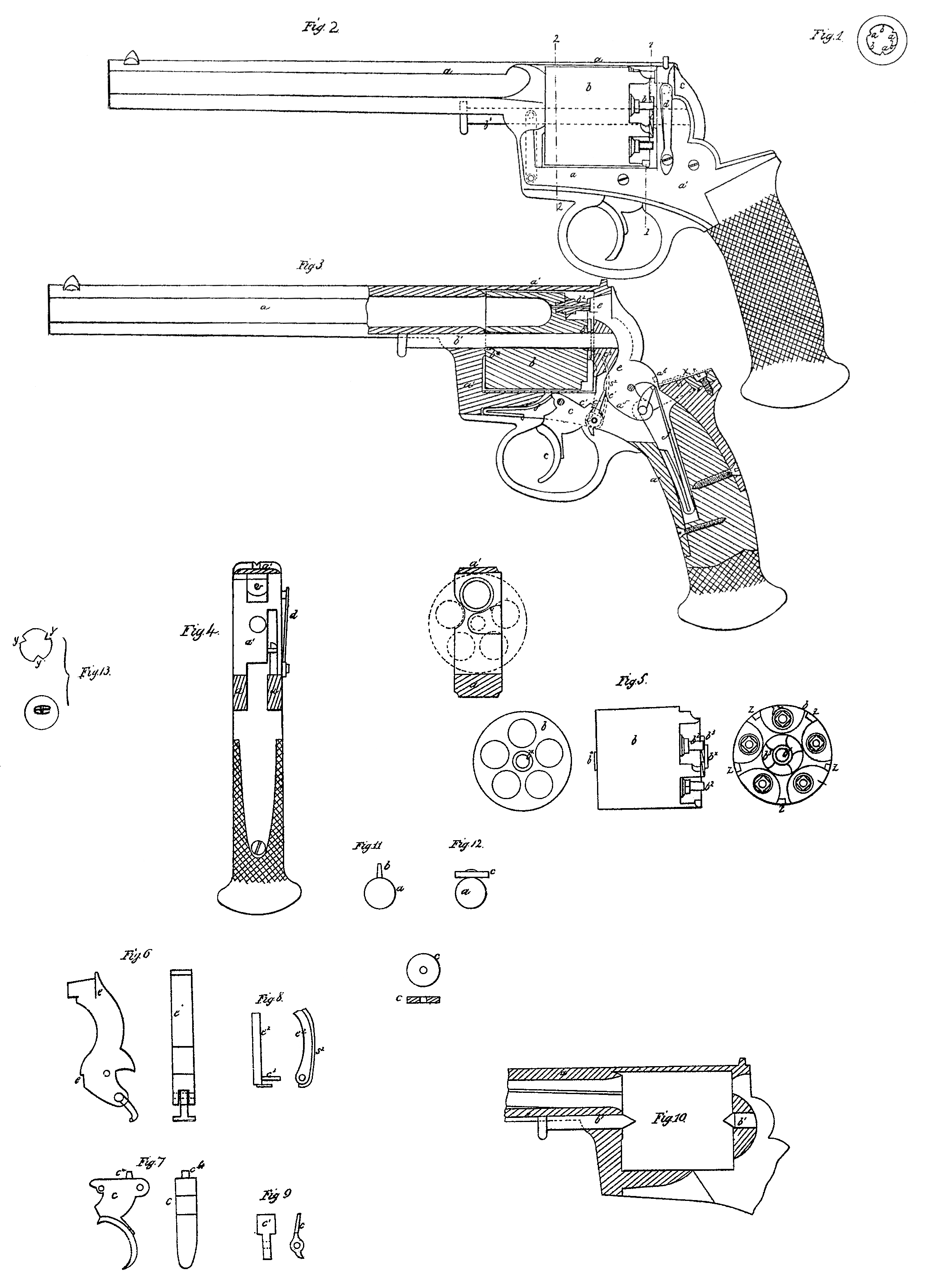
The improvements (exhibited by the drawings) in the construction of rifle-barrels of fire-arms consist in forming raised ridges on the inner surface of such barrels in place of grooves or the plowed hollows commonly called “rifling,” and I prefer to form such ridges angular, as shown by the section of a barrel at Figure 1; but the shape and number of such ridges may be varied.
at a are the projecting ridges, which are to be made in a helical direction, similar to that heretofore resorted to for the grooves. b b are the grooves, which have a considerable extent of width as compared with the more narrow ridges.
Heretofore the hollows or grooves were narrow as compared with the projecting parts, and in fact as heretofore constructed the diameter of the bore of the barrel was taken across from the raised or internal projecting parts, the grooves being external of the measured diameter.
According to my mode of construction the measured diameter of the bore of the barrel is from b to b, the ridges being projecting interiorly. I prefer to employ three such ridges at equal distances apart; but this may, as before stated, be varied, and the balls used with such barrels should be cast with notches or grooves, as seen at y y in Fig. 13, to fit the barrels, and I have found that by such means no patches are required to be used with the balls.
Fig. 2 shows a side view, Fig. 3 a longitudinal section, Fig. 4 a cross-section, of a fire-arm constructed on my improved plan; Fig. 5, separate views of the revolving chambers; and Figs. 6, 7, 8, and 9 show some of the parts separately of a gun or pistol having my improvements applied thereto.
a is the tube or barrel, of any suitable length, and open at each end. The upper part of the barrel, at the back end, is continued at a’. It descends at right angles, returns, rises again, and joins the under side of the barrel, forming in one piece of metal a rectangular opening, in which the series or magazine of chambers containing the several charges revolves, to be successively brought opposite to the barrel a and discharged, as hereinafter explained.
The revolving magazine b is supported by and revolves on the axis b’, which slides into a groove on the under side of the barrel through the rectangular frame a’, the rear end of it being supported in the back part of the frame, which, as before stated, is solid or in one piece with the barrel, as shown. The magazine or series of revolving chambers may be readily detached from the opening through the frame by drawing the axis b’ out toward the mouth of the barrel. The series of revolving chambers may be supported on two conical centers, one or both of which may be capable of sliding out, so as to detach the series of chambers, as shown in section at Fig. 10. The back of each chamber is recessed, as shown, to receive the nipples b^2. At the back end of the series of chambers is formed a ratchet, b^3, of teeth, into which the perpendicular ratchet-impelling lever or pawl c^2 (shown in red lines) works, the other end of said pawl being connected to the trigger c by the pin c^3, which forms an axis for the sear c’, which takes into a bent or recess, et, formed in the front part of the cock or hammer e. When the trigger is pulled back the sear c’ lifts the hammer to a sufficient height for the action of the mainspring j to give it sufficient force to explode the cap, and the sear c’ is thrown out of the recess et by the projecting angular part a^5 of the cock, as shown, when the cock is forced back to the fullest extent. The hammer strikes the cap in a horizontal direction, the striking part passing through a hole formed in the hinder part of the frame a’. The spring-bolt d, Figs. 2 and 4, when pressed inward, comes against a suitable shoulder or recess formed on the hammer-head and retains it back while the revolving chambers are being charged. The object of this spring-bolt is to prevent the hammer from discharging the cap by an accidental blow or when disengaging the part b.
f is a spring to return or restore the trigger and parts attached to their original positions after each discharge.
c^4 is a stud on the trigger, which stud enters any one of a series of recesses, z z z, Fig. 5, (made on the outer circumference of the revolving chambers,) at the time each chamber is brought in line with the barrel a. The stud retains the magazine in place while the discharge occurs.
b^x are collars, which are affixed to and revolve with the part b to reduce the friction on the axis b’.
I sometimes make the balls or projectiles with tangs and fix thereon a wad or pellet composed of felt or other fibrous material. Figs. 11 and 12 show a ball constructed in such manner. a is the ball, cast with a tang, b. c is the pellet or wad, composed of felt or other fibrous material, fixed to the ball by riveting down on it the tang after having placed the wad thereon.
I would here remark that it is very desirable to use balls and Wads thus made and combined with fire-arms constructed as described, as portions of the paper commonly used are liable to be blown between the revolving chambers and the barrel, so as to impede the action of the revolving chambers.
Having herein described the nature of my invention and the manner of performing the same, I would have it understood that I make no claim to the several mechanical parts separately; nor do I confine myself to the several details so long as the peculiar character of any part of my invention be retained. In my said pistol or fire-arm the cock is placed behind and entirely below the top edge or line of sight of the piece; and in order to gain this advantage and to apply to the pistol a mechanism or combination of mechanisms by which the cock can be raised, discharged, and the parts restored during and by a simple back-pull of the trigger and release and forward movement of it, a peculiar construction and arrangement of the trigger c, the sear, the notch or shoulder e’ of the cock, the spring f, and the cock or hammer and mainspring j becomes necessary, such being exhibited in Fig. 3; and I would remark that in connection with such arrangement of such parts there is also shown in such figure, and partially in Fig. 5, a peculiar arrangement of the impelling-pawl c^2, the ratchet b^3, the stud c^4, and the notches z z z, or, in other words, of the machinery by which the rotation and locking of the magazine are effected. The pawl should be pressed toward the ratchet by a spring suitably applied, as seen at s^2.
I claim—
1. The improvement of combining with the frame a’ and the hammer e the spring d, for holding the hammer back, as stated.
2.The sear c’, attached to the trigger by a swivel-joint and acting on the hammer e, substantially as herein described.
3. The stop or projection c^4 on the trigger, for holding the chambers in position when firing, substantially as herein described.
ROBERT ADAMS,
Witnesses:
Joseph Marquette,
William Ewing.