
Britain 5031
A.D. 1878, 9th December. № 5031.
Fire-arms.
LETTERS PATENT to Michael Kaufmann, of Fenchurch Street, in the City of London, and Kingdom of England, and Julien Warnant, of Hognée, Commune of Cheratte, in the Kingdom of Belgium, for the Invention of “Improvements in Fire-arms.”
Sealed the 21st February 1879, and dated the 9th December 1878.
PROVISIONAL SPECIFICATION left by the said Michael Kaufmann and Julien Warnant at the Office of the Commissioners of Patents on the 9th December 1878.
MICHAEL KAUFMANN, of Fenchurch Street, in the City of London, and Kingdom of England, and JULIEN WarNant, of Hognée, Commune of Cheratte, in the Kingdom of Belgium,”Improvements in Fire-arms.”
Our Invention relates to improvements on the system of fire-arms patented by Amédée Thornton de Mouncie, August 14th, 1876, No. 3206, which Letters Patent have been transferred by the said Thornton de Mouncie to the above-named Michael Kaufmann.
We propose to provide the fire-arm with a lock of a stronger and more substantial construction, with less friction in the movements of its mechanism, consequently of greater durability, and so constructed that the hammer wields a greatly increased force in its descent on the cartridges, thereby effectually preventing all chance of a misfire even under unfavourable circumstances, whilst much unnecessary force of the lower branch of the spring used for producing the re-action or rebound of the hammer is suppressed, and the power of the pull of the trigger on the finger is very greatly decreased, which prevents the party using the fire-arm from being quickly fatigued, and renders it more serviceable.
We use no screws and no additional axles or pivots for our lock beyond the two which support the hammer and the trigger. These we leave solid, but prolong them in such manner that a new piece, which we call an “arm,” shall have for its axle or pivot that of the hammer, and holes are made in the cover plate of the lock to permit the two axles to pass through and to be securely held therein.
The “arm” is made of one solid piece of metal pivoting on the axle of the hammer and projected therefrom, slightly inclined at its base to bear on the inclined plane of the countersunk part of the lever, holding it in its proper position for effecting the rotation of the cylinder.
On the face of the “arm,” from its base towards and near its axle, is an elevation or projection on which the mainspring is sustained. We use a spring with two branches which approach each other closely when the hammer is carried to full cock.
The upper branch produces the blow of the hammer on the cartridge, and the lower branch, made of one piece of metal without slot, opening, or groove, and provided with a safety stop, rests on and is supported by the elevation or projection on the part which we call an “arm.”
This spring is of a more simple and of a more solid construction, and more easily manufactured than the one in the original Patent referred to, the weakest part of which is in our system entirely dispensed with.
The lower branch of the spring acting on the “arm” after the fall of the hammer on the cartridge causes the lever pivoted on the trigger to descend to its normal position, whilst the safety stop of the spring engaging with the base of the hammer lifts the hammer clear of the cartridge.
The construction is so arranged that the movement of the lower branch of the spring on the “arm” is very slight, and consequently there is very little friction; ‘and much of the weight of the lower branch of the spring, which presses firmly on the “arm,” being borne by the axle on which the “arm” pivots, very little power is required to put the trigger in-motion for full cocking and firing the weapon. At the same time the suspension of the lower branch of the spring brings it somewhat near to the upper branch, the latter thereby receiving an increase of power which causes the augmented force of the blow of the hammer-on the cartridges, as already stated.
There are only five pieces in the whole of the mechanism of the lock, viz., the hammer, the “arm,” the spring, the trigger, and the lever; the lock being so combined and constructed that it may be rapidly taken to pieces and again put together when required to be cleaned, and although no screw is used, each part is securely held in its place.
SPECIFICATION in pursuance of the conditions of the Letters Patent filed by the said Michael Kaufmann and Julien Warnant in the Great Seal Patent Office on the 21st April 1879.
Michael Kaufmann, of Fenchurch Street, in the City of London, and Kingdom of England, and: JuLien Warnant, of Hogndée, Commune of Cheratte, in the Kingdom of Belgium. “Improvements in Fire-arms.”
Our present Invention relates to locks for fire-arms, and consists of certain improvements upon that described in Patent No. 3206, dated August 14th, 1876.
Although our said Invention is adapted for use in any kind of percussion fire-arm it is especially to be applied to revolvers, and is fully, clearly, and exactly described as follows, reference being had to the accompanying Drawings, in which,—
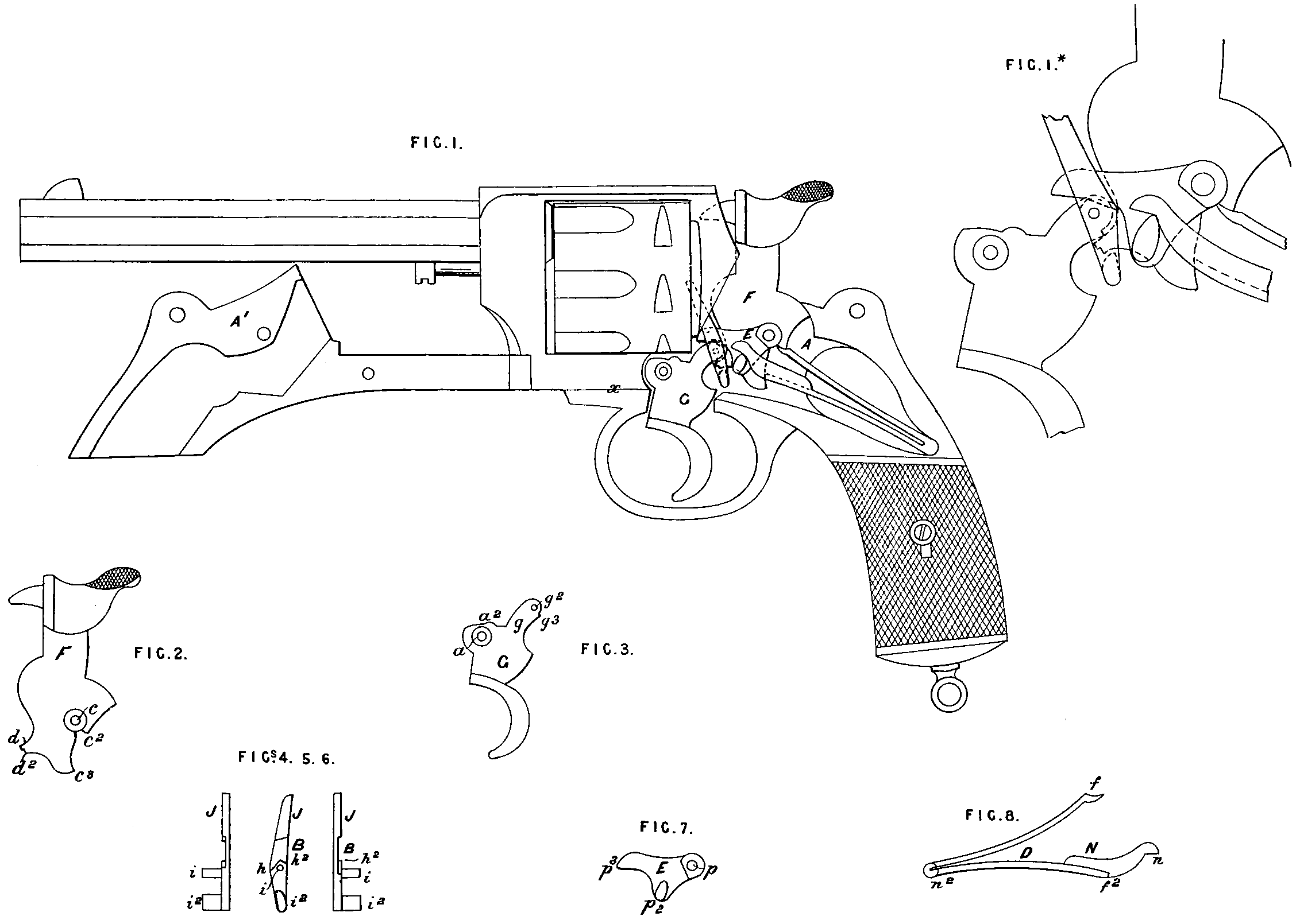
Figure 1 represents a side elevation of the revolver with the cover plate laid back, shewing all the parts of the lock in their proper juxtaposition, the hammer resting in its normal place, and Fig. 1* an enlarged view of the action.
Figure 2 is a side elevation of the hammer.
Figure 3, a side elevation of the trigger.
Figs. 4, 5, and 6 are respectively front, side, and rear elevations of the pawl or lever.
Figure 7 is a top plan of the arm.
Figure 8, a bottom plan of the mainspring.
In the Drawings, A represents the main frame of the weapon provided with two studs-or pivots, the one for the hammer and arm, and the other for the trigger. The cover plate A¹ is provided with. corresponding holes, into which, when the plate is closed, the trigger and hammer pivots enter and are securely held.
The hammer F is provided with the ordinary point for exploding the cartridge and with roughened thumb-piece. A hole is formed in it for the central pivot at c and on the rear side of the hammer is formed a bearing c² for the mainspring, and a tail piece c³. On the forward side of the hammer is a projection d², having a notch d for engagement with the trigger when the hammer is thrown back by the thumb of the operator ; the said projection serving also as a means for effecting the so-called “self-cocking” of the weapon, as will be herein-after set forth.
The trigger G is of the shape illustrated, and is perforated at a for the insertion of the pivot. A small lug or detent a? is formed on the upper surface of the trigger, which enters one of the notches upon the cylinder when the weapon is full-cocked. A projection g, perforated at g² for the pawl pivot, has a notch g³ adapted to engage with’ the projection on the forward side of the hammer.
J represents the pawl or lever (see Figures 4, 5, and 6), which consists of a flat steel bar countersunk on one side, as shewn at B, and provided with a pivot i adapted to enter the hole g² in the trigger. A lug i² projects from the lower end of the pawl or lever subserving the double function of locking and self-cocking the hammer. The lower end or bottom of the countersunk part B consists of two planes h inclined, as shewn, whose apex h² is forward of the pivot i, the object of which construction will be presently evident.
The mainspring D consists of two leaves or branches, the one adapted to engage at f with the bearing c² upon the hammer, and the other having at f² a safety stop which serves to effect the rebound of the hammer. A lug n² is provided at the junction of the leaves, and is adapted to enter a step or hole in the main frame.
It will be observed that the projection d² of the hammer occupies a position between the projection g of the trigger and the lug i² of the pawl or lever, fitting snugly between them.
Instead of the arm of the mainspring engaging directly with the pawl, however, as in the Invention, No, 3206⁷⁶, the arm N of the mainspring terminates in a bearing n which engages with the arm E, and this constitutes the salient feature of our present Invention.
This piece which we term the “arm” is represented in Figures 1 and 7 of the Drawings. It consists of a suitable piece of steel having a hole p for the hammer pivot, a lug or elevation p² upon which the end of the mainspring bears, and a projection p³ which rests upon the inclined plane h of the pawl, and holds. the latter in proper position.
The operation of the lock is as follows:—
Upon cocking the weapon by the thumb of the operator, the projection d² of the hammer engages with the end g of the trigger which carries up the pawl, and with it the arm, thereby compressing the mainspring, and at. the same time effects the rotation of the cylinder. Finally, the projected notch d of the hammer falls into the trigger notch g³, and the weapon is full cocked.
When the trigger is retracted the notches d and g³ come out of engagement, and the hammer is released and falls. Upon releasing the trigger, the pressure of the mainspring, delivered through the medium of the arm acting upon the pawl, carries the trigger forward and the pawl downward until its lug i² passes the projection d² of the hammer, when the pawl tilts forward owing to the arrangement of the bearing h and coming under the projection d² locks the hammer. Coincidently with the descent of the pawl, the safety stop f? of the mainspring coming to bear upon the tail piece c³ of the hammer effects the rebound of the hammer. In this position the hammer is, positively locked, and an accidental discharge of a cartridge practically out of the question, as it is clear that the hammer cannot by any possibility be made to reach a cartridge without being first raised to full-cock, by reason of the bringing up of the trigger against the main frame a of the weapon.
It will have been made evident from the foregoing. description of the parts that the lock is double-acting; and when used, as a self-cocker, the operation may be briefly described as follows:—
The trigger being retracted lifts the pawl, and its lug i² engages with the projection d² of the hammer, which is thereby raised until the lug i² passes from under the projection d³, when the hammer being released falls. During the lifting of the pawl it rotates the cylinder in the usual way, and at the same time the former, carrying with it the arm, compresses the mainspring, the lower leaf of which bearing the safety stop, being then raised to its maximum, it cannot impede the fall of the hammer. After the descent of the latter the trigger is released, when the rebound and locking of the hammer is effected, as already described.
Our lock being in many respects the same in construction as in the Invention described in Patent, No. 3206, of 1876, the advantages therein are likewise to be found in our system of fire-arms, viz,:—
The peculiar construction and mutual adaptation of the working parts. The rebounding hammer actuated by the safety stop of the mainspring. The absence of any other spring or parts which have heretofore been necessarily delicate and frail, and liable to get out of repair. The very few pieces of which the mechanism consists, and their simplicity, strength, durability, and effectiveness. Lastly, that the lock is readily accessible, not a single screw used in it, and so constructed and arranged that its various parts are rapidly and easily taken to pieces and put together.
It is specially to be noted that in our present Invention the arm or, pivoted connection E subserves an important function in the lock; it acts with a minimum pressure on the pawl or lever, whilst more efficiently regulating the bearing of the latter upon the ratchet piece of the cylinder, and it (the arm) equalizes the trigger pull in self-cocking the weapon, which are most important ends if accuracy of aim and facility of action may be considered an object. The piece or arm E. is in effect a bent lever, and its operation in equalizing the trigger pull depends upon the relative acting distances of the power and weight and their altitude from the hammer pivot.
It is also important to observe that in our Invention the mainspring is exceedingly simple and strong, and so disposed as to have very little movement in its action, and hardly any friction.
As herein-before stated, our Invention is adapted for use in any kind of percussion fire-arm. When not used in a revolving fire-arm, of course the pawl would be a superfluity, and might either be dispensed with entirely, the “arm” being made to bear upon a suitable projection on the trigger, or, if the self-cocking feature is desired, the pawl might be simply cut off above the pivot entering the trigger.
Having now described and ascertained the nature of our said Invention, and in what manner the same is or may be performed, what we
Claim as secured to us by the herein-before in part recited Letters Patent is,—
Firstly. In a lock for fire-arms, a mainspring adapted to effect the rebound of the hammer, and actuating the trigger through the medium of a pivoted connection H, substantially as set forth.
Secondly. An arm or pivoted connection E bearing upon the pawl and actuated by the mainspring, substantially as set forth.
Thirdly. The lock for revolving fire-arms herein described, consisting of hammer, trigger, pawl, arm, and mainspring, the latter serving to effect the rebound of the hammer and actuating all of the: parts named, substantially as and for the purposes set forth.
In witness whereof, I, the said Michael Kaufmann, have hereunto set my hand and seal, this Eighth day of April, in the year of our Lord One thousand eight hundred and seventy-nine.
MICHAEL KAUFMANN. (L.S.)
Witness,
W. E, Gena,
Patent Agent,
11, Wellington St,
W.C.