
Britain 2855
A.D. 1879, 14th Jozy. № 2855.
Fire-arms and Ordnance.
LETTERS PATENT to William Tranter, of Birmingham, in the County of Warwick, Gun Maker, for the Invention of “Improvements in Fire-arms and Ordnance.”
Sealed the 12th September 1879, and dated the 14th July 1879.
PROVISIONAL SPECIFICATION left by the said William Tranter at the Office of the Commissioners of Patents on the 14th July 1879.
William Tranter, of Birmingham, in the County of Warwick, Gun Maker. “Improvements in Fire-arms and Ordnance.”
The first part of my Invention relates to repeating arms or revolvers, and consists in making the frame of the pistol with a joint at the lower part, the top thereof having in it a slot to fit on a projection on the back part of the frame. On one or both sides of the top strap is formed a projection to be acted upon by a hooked lever for holding the top strap in its position.
The said hooked lever has a solid axis pin, which passes through the body of the pistol, and is made to act on the side of the pistol, and is actuated by a double spring let into the shield for the chamber.
By this arrangement the pistol can be opened and closed, and the empty cases discharged with one hand.
The joint of the frame is formed by the outside lugs thereof being solid with the barrel, the inside part of the joint being formed solid with the frame.
In that part of the joint solid with the frame of the pistol is formed a recess and stud round the axis of the joint for the purpose of carrying the lever which acts upon the extractor. This lever has in it a notch, into which a catch is made to fall in order to fix it in the required position.
The socket or tube which carries the chamber is fixed in its required position by means of a hooked lever taking into a notch formed therein. This hooked lever is made to work in a slot formed in a stud fixed in the centre hole of the barrel.
The hammer is formed with a notch in the top part of it for additional security in retaining the top strap in its position. The hammer is also formed so that the mainspring can act upon it directly without a swivel, the bottom part of the same being formed so that it can be acted upon by a lever worked in connection with the mainspring. The said lever, besides being made to act upon the hammer, may be formed to act upon the lifter or catch, or both together, or upon a stud on the trigger
The catch is formed with a lip at the top part of it to prevent its falling into the notch or bent too far.
A stop for fixing the chamber maybe arranged similar to those in my former Patents, No. 1613 (I856) and No. 1862 (1863).
The second part of my Invention relates to a repeating arm formed with a number of barrels with chambers placed longitudinally in a frame, and with bolts and strikers similar to my Invention No. 2113, ¹⁸⁵⁶. The bolts and strikers are actuated by a lever moving in a bar placed across the frame, and actuating a crank working in a slot partly straight and partly elliptical, which is made to form part of the frame for actuating the bolts and sliding in the frame holding the chambers of the barrels.
In connection with the lever or frame a slide is worked for fixing the bolts of the chambers during the time of firing. . Extractors are fitted similar to my Patent No. 2113, ¹⁸⁵⁶, and a thrower is formed to work in connection with the lever or bolts which forces the empty cases out of the chambers at the bottom of the same. A slide is formed to work over the top openings of the chambers to drop the charges into the chambers as required, and for this purpose is formed with slanted or diagonal apertures.
The third part of my Invention relates to a method of closing the breech end of a barrel when required to load at the breech. A bolt is made to work in a slot formed at right angles to the bore of the barrel, and moved by means of a screw placed on the underside of the bolt, and working partly in the bolt and partly out, and actuated by a handle on the side of the barrel. A stopper is formed to close the breech end, which is fixed during the time of firing by the bolt. This stopper may be hinged at the top to enable it to work with facility.
The said method of closing the breech end is also applicable to ordnance.
SPECIFICATION in pursuance of the conditions of. the Letters Patent filed by the said William Tranter in the Great Seal Patent Office on the 14th January 1880.
William Tranter, of Birmingham, in the County of Warwick, Gun Maker, “Improvements in Fire-arms and Ordnance.”
The first part of my Invention relates to repeating arms or revolvers, and consists in making the frame of the pistol with,a joint at the lower part, the top thereof having in it a slot to fit on a projection on the back part of the frame. On one or both sides of the top strap is formed a projection to be acted upon by a hooked lever for holding the top strap in its position.
The said hooked lever has a solid axis pin, which passes through the body of the pistol, and is made to act on the side of the pistol, and is actuated by a double spring let into the shield for the chamber.
By this arrangement the pistol can be opened and closed, and the empty cases discharged with one hand.
The joint of the frame is formed by the outside lugs thereof being solid with the barrel, the inside part of the joint being formed solid with the frame.
In that part of the joint solid with the frame of the pistol is formed a recess and: stud round the axis of the joint for the purpose of carrying the lever which acts upon the extractor. This lever has in it a notch, into which a catch is made to fall in order to fix it in the required position.
The socket or tube which carries the chamber is fixed in its required position by means of a hooked lever taking into a notch formed therein. This hooked lever is made to work in a slot formed in a stud fixed in the centre hole of the barrel.
The hammer is formed with a notch in the top part of it for additional security in retaining the top strap in its position. The hammer is also formed so that the mainspring can act upon it directly, without a swivel, the bottom part of the same being formed so that it can be acted upon by a lever worked in connection with the mainspring. The said lever besides being made to act upon the hammer may be formed to act upon the lifter or catch, or both together, or upon a stud on the trigger. The catch is formed with a lip at the top part of it to prevent its falling into the notch or bent too far.
A stop for fixing the chamber may be arranged similar to those in my former Patents, No. 1913 (1856) and No. 1862 (1863).
The second part of my Invention relates to a repeating arm formed with a number of barrels with chambers placed longitudinally in a frame, and with bolts and strikers similar to my Patent No. 2113, ⁵⁶. The bolts and strikers are actuated by a lever moving in a bar placed across the frame, and actuating a crank working in a slot partly straight and partly elliptical, which is made to form part of the frame for actuating the bolts, and sliding in the frame holding the chambers of the barrels.
In connection with the lever or frame a slide is worked for fixing the bolts of the chambers during the time of firing. Extractors are fitted similar to my Patent No. 2113, ¹⁸⁵⁶, and a thrower is formed to work in connection with the lever or bolts which forces the empty cases out of the chamber at the bottom of the same. A slide is formed to work under a hopper and over the top openings of the chambers to drop the charges into the chambers as required, and for this purpose is formed with slanted or diagonal apertures.
The third part of my Invention relates to a method of closing the breach end of a barrel when required to load at the breach. A bolt is made to work in a slot formed at right angles to the bore of the barrel, and moved by means of a screw placed on the under aide of the bolt, and working partly in the bolt and partly out, and actuated by aa handle on the side of the barrel. A stopper is formed to close the breach end, which is fixed in the bore of the barrel during the time of firing by the bolt. This stopper may be hinged at the top to enable it to work with facility.
The said method of closing the breech end is also applicable to ordnance.
Having thus stated the nature of the said Invention I will proceed to describe more particularly in what manner. the same is to be performed by the aid of the accompanying Drawings, in which are represented some of the parts of fire arms and ordnance above referred to.
DESCRIPTION OF THE DRAWINGS.
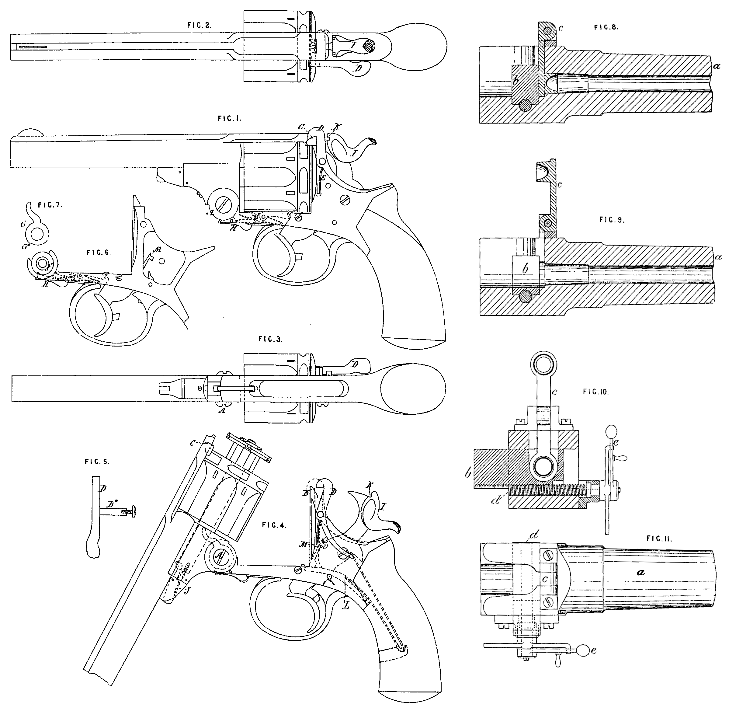
Figures 1 to 7 relate to the first part of my Invention.
Figure 1 is an elevation of a revolver with my improvements applied thereto; Figure 2 is a top plan, and Figure 8 an underneath plan of the same; Figure 4 is an elevation showing the pistol as opened for loading.
A is the joint for the barrel to hinge upon; B is a projection on the back part of the frame for a slot in the top thereof to fit on; C is a projection on the top strap to be acted upon by the hooked lever D for holding the top strap in position. This hooked lever, which is shown detached in Figure 5, has a solid axis pin D*, which passes through the body of the pistol, and the lever is made to act on the side of the pistol, being actuated by a double spring E let into the shield for the chamber. A hooked lever D may be applied to each side of the top strap. The outside lugs of the joint A are solid with the barrel, and the inside part of the joint is solid with the frame, as shown in Figure 3. F, Figure 6, is a recess formed round the axis of the joint for the purpose of carrying the lever G, shown detached in Figure 7, which lever is caused to act on’ the extractor, as shown by dotted lines in Figure 4; G* is a notch in the lever G, into which a catch H is made to fall in order to fix the lever in its required-position.
J is a hooked lever for fixing in its required position the socket or tube which carries the chamber by taking into a notch formed in the axis tube, such hooked lever being made to work in a slot formed in a stud fixed in the centre hole of the barrel.
I is the hammer, which is formed with a notch K-in the top part of it for additional security in retaining the top strap in position. The hammer is also formed so that the mainspring can act upon it directly without a swivel, as shown in Figure 4, the bottom part of the hammer being formed so as to be acted upon by the lever L in connection with the mainspring.
This lever L is also formed to act on the trigger by means of a stud, ag shown, or it may be formed to act on the lifter and catch simultaneously with the trigger. For this purpose the lever L is made to work inside the lifter and on a stud formed on the catch near its joint on the trigger. M is a lip at the top part of the catch to prevent it from falling too far into the notch or bent in the chamber.
N is a stop for fixing the chamber, such stop being acted upon by the trigger and a spring, as shown by dotted lines in Figure 1.
The second part of my Invention will be sufficiently understood from the description quoted above from the Provisional Specification without the aid of Drawing
Figures 8 to 11 relate to the third part of my Invention as applied to ordnance; Figure 8 is a longitudinal section with the stopper fixed in the barrel by the sliding bolt.
Figure 9 is a section with the bolt withdrawn and the stopper removed from the barrel; Figure 10 is a transverse section showing the bolt withdrawn by the screw and the stopper removed from the bore, thereby rendering the barrel open from end to end; Figure 11 is a plan view showing the barrel closed with the bolt.
a is the barrel; is the bolt, on the lower side of which is formed a female screw corresponding with the screw d, This female screw formed in the bolt only extends to about half the circle, and there is a groove formed in the end of the bolt, as shewn in Figure 10, to facilitate the loading of the gun.
The screw d by which the bolt is worked is formed with a square thread, and turns round in a smooth groove formed in the breech end of the barrel, and is retained in its position by a collar formed on the screw and working in a bracket placed on the side of the barrel, and with a fixed and loose handle e to move the screw as required.
c is a stopper for preventing the escape of gas from the breech end.
Having thus described the nature of the said Invention and in what manner the same is to be performed, I hereby declare that what I claim as of my Invention is,—
First. The joint A of the frame as represented and described.
Secondly. The hooked lever D acted upon by a spring, the said lever hooking on to a stud formed on the side of the top strap, as represented and described.
Thirdly. The lever J acting as a fixture for the axis tube as represented and described.
Fourthly. The stop N for fixing the chamber after firing, as represented and described.
Fifthly. The lip M on the top of the catch and the lever L acting upon the lifter, catch, and trigger, as represented and described.
Sixthly. The general combination of the parts represented in Figures 1 to 7, and described.
Seventhly. The second part of the Invention as described.
And, Lastly. The third part of the Invention as represented and described.
In witness whereof, I, the said William Tranter, have hereunto set my hand and seal, the Thirteenth day of January, in the year of our Lord One thousand eight hundred and eighty.
WILLIAM TRANTER. (L.S.)
Witness,
WILLIAM SPENCE,
8, Quality Court,
Chancery Lane.