
US 529877
UNITED STATES PATENT OFFICE.
LOUIS LEOPOLD PICARD, OF PARIS, FRANCE.
REVOLVER WITH KNIFE ATTACHMENT.
SPECIFICATION forming part of Letters Patent No. 529,877, dated November 27, 1894.
Application filed April 17, 1893. Serial No. 470,746. (No model.) Patented in France July 6, 1889, No. 199,422, and in Belgium July 6, 1889, No. 86,888.
To all whom it may concern:
Be it known that I, LOUIS LEOPOLD PICARD, a citizen of the French Republic, residing at the city of Paris, in said Republic, have invented a new and useful Improvement in Revolving Firearms, (for which I have obtained a Patent in France, No. 199,422, dated July 6, 1889, and in Belgium, No. 86,888, dated July 6, 1889,) of which the following is a specification.
This invention relates to the mechanism of a revolving fire-arm whereby the rotation of the cylinder, the cocking and firing are all produced by the movements of a trigger, and it further relates to the combination with a revolving pistol of a knife with a folding blade so constructed and arranged in the pistol that when its blade is folded it does not add to the length of the pistol and it cannot be opened accidentally.
The accompanying drawings represent a revolving pistol with a knife blade mounted according to my system.
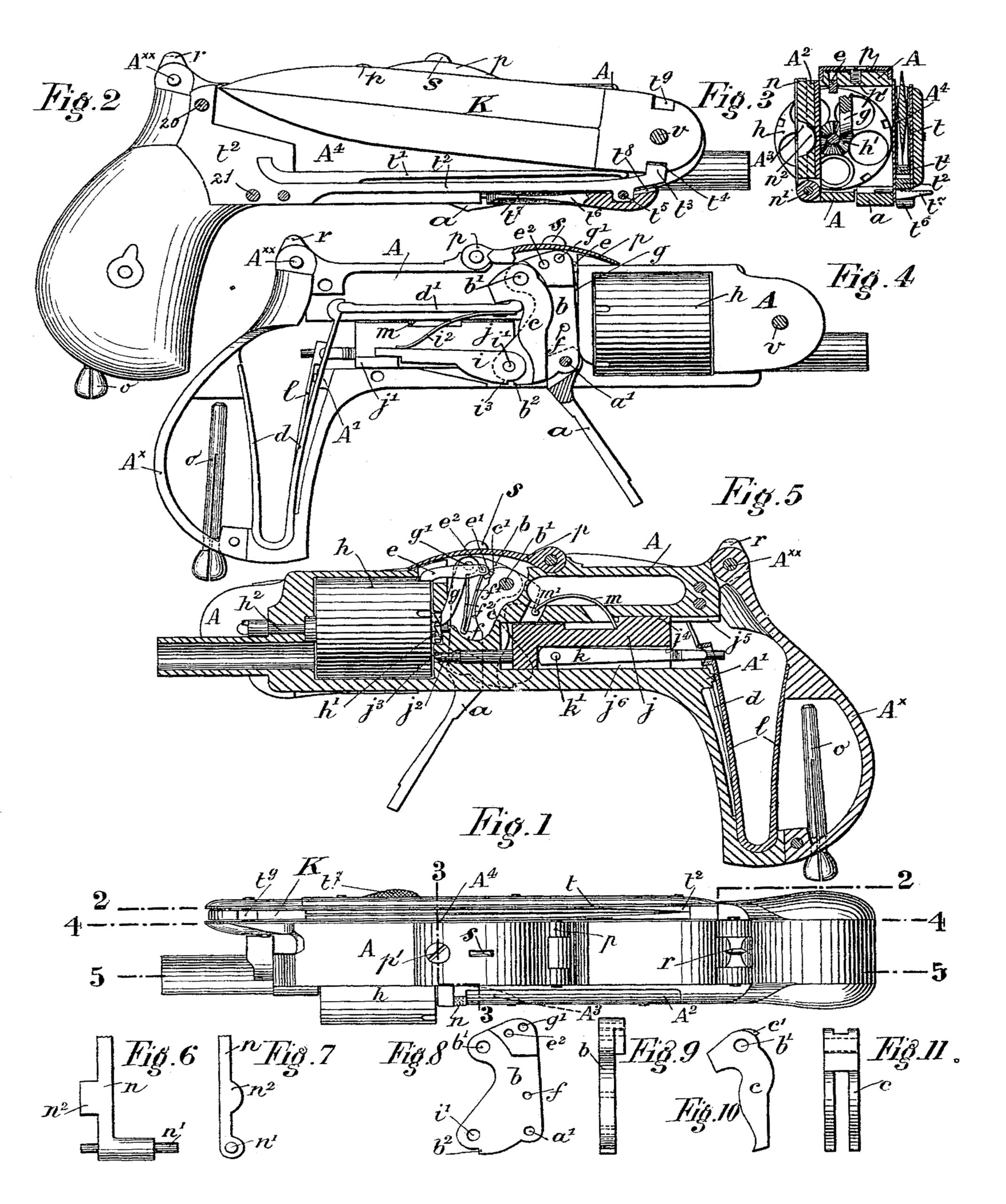
Figure 1 is a plan or top view of a pistol embodying my invention. Fig. 2 represents a right hand side view of the pistol having removed from it the side plate which covers the knife, or the said figure may be said to represent a longitudinal section taken parallel with the side of the pistol in the plane indicated by the line 2, 2, of Fig.1. Fig. 3 represents a transverse section taken in the line 3, 3, 0f Fig. 1. Fig. 4 represents a right hand side view of the pistol having removed from it the whole of the knife and its especial appurtenances, or the said figure may be said to represent a longitudinal section parallel with the side of the pistol taken in the line 4, 4, of
Fig. 1. Fig. 5 represents a longitudinal section in the line 5, 5, of Fig. 1. Figs. 6 and 7 represent respectively side and rear views of the charging gate. Figs. 8 and 9 are respectively side and rear views of what I call the trigger-plate. Figs. 10 and 11 are respectively side and rear views of what I call the trigger-fork.
Similar letters and numerals of reference designate corresponding parts in all the figures.
In referring to these figures I will first describe in detail the construction and various operations of the arm beginning with the revolving mechanism.
The trigger a has a head in the form of a fork which embraces the lower part of a pendent plate b which I designate by the name of “trigger-plate” and upon which the trigger is articulated at a’. This trigger-plate b is articulated at b’ upon the frame A of the arm and is embraced throughout nearly its entire height between the two branches of a pendent-fork c which is pivoted upon the same fixed pivot or pin b’ as the trigger-plate 6 in such manner as to hang freely behind the head of the trigger. The lower part of this pendent-fork c is pressed against the head of the trigger by a two-branched spring d (Fig. 4) which constitutes the trigger spring and which is lodged in the stock of the pistol on the right side. This spring has its abutment in the butt-plate Ax of the stock which is hinged at Axx upon the frame A in such manner that by turning it down to put it in place at the time of assembling the parts of the
arm the spring is set to the necessary tension. The said spring d acts through the intermediation of a rod d’ which abuts at its front end against the two branches of the fork c while its other end is received in the claw of the spring d.
As may be easily seen in the drawings (Fig. 4), as soon as the trigger is pulled back by the finger it commences, by turning about its articulation a’, to give to the fork c a slight movement of rotation about its fixed pivot b’. The tooth c’ on the upper part of the said fork is then depressed and presses against the back of the claw e’ of a small lever e which serves as the stop to the cylinder. This lever e is articulated at e2 upon the trigger-plate b and its free extremity is normally engaged in one of the notches, equal in number to that of the chambers of the cylinder, upon the periphery of the latter; and it is maintained in this position by a two-branched spring f’ f2 of which the head is articulated at f upon the trigger-plate and of which one of the branches f’ presses against the front face of the claw e’ of the stop lever e. The cylinder is then free to be turned as will now be explained.
Up to that stage of the operation last mentioned the trigger-plate d has not moved but if the backward pressure on the trigger is continued all the trigger mechanism above described turns about the fixed pivot b’, and the lower part of the trigger-plate is drawn backward while the upper angle of the said plate situated in front of the pivot b’ is lowered. To this upper angle is articulated at g’ a pawl g of which the free extremity is always pressing in one of the notches h’ of the ratchet h, on the cylinder. This pawl g is constantly pressed against the ratchet h by the branch f2 of the spring f’ f2. The cylinder is then caused to turn about its central arbor h2. During this turning movement the stop e is depressed with the upper angle of the trigger-plate upon which it is mounted; and it comes into contact with the cylinder, upon the top of which it bears in such manner as to act as a brake, until the succeeding notch is presented before it, when it drops into the said notch and stops the cylinder which it maintains stationary in the proper position to present a cartridge opposite the barrel.
I will now describe the firing mechanism. In moving backward as above described, the lower part of the trigger-plate carries away with it the sear i which is articulated to it at a’ (see Fig. 5) and in the free rear end of which is a notch in which engages a lateral projection j’ on the rear part of the firing ping. The firing pin is thus pushed backward with the sear. As the articulation i’ of the sear i moves back it is also slightly raised, but as the sear is capable of turning freely with respect to the trigger-plate b about its articulation i, its extremity is kept pressed down in engagement with the firing pin by means of a spring i2 affixed upon the rod d’ above mentioned. It thus results that while moved backward the sear tends to assume a horizontal position while the trigger-plate continues to rise until the projection b2 upon the lower edge of the said plate meets another projection i3 arranged facing it on the sear; from that time the sear becoming rigid with the trigger-plate and cannot turn about its axis of articulation i’, but rises, as it were, all in a piece with the trigger-plate. Consequently its notch soon escapes from the projection j’ of the firing pin and the latter ceases to be carried backward.
I will now describe how the firing pin j is thrown forward to detonate the priming. The greater portion of the length of the said pin j is in the form of a square block but it terminates in the front in the form of a needle j2. It is guided in part by the passage of the needle through a hole j3 in the frame and in part by a tongue j4 upon the upper face of the block which runs in a guide groove j5 in the frame. The block has in its bottom a cavity j6 in which works a rod k of which one of the extremities is attached to the block at k’ and the other extremity is received in a notch in the end of the two-branched mainspring l (see Fig. 5) lodged in the stock on the left hand side and having its bearing against a shoulder in the butt-plate Ax by which it is set to tension in the same manner as the trigger spring, as hereinbefore described. The tension of this spring is still further increased by the drawing back of the firing pin. Consequently as soon as the firing pin is left to itself by its escape from the notch of the sear the said spring projects its front branch forcibly forward. This forward movement is stopped by the shoulder A’ in the frame and if the firing pin were stopped at the same time its point would be at about a millimeter from the cartridge; but it continues its movement by reason of the momentum acquired and its point is thereby caused to strike the priming and produce the discharge. After firing, the firing-pin is brought back to its position of rest by a spring m of arched form (see Fig. 5) which is affixed at one end to the frame at m’ and the other end of which is free but engaged in a groove made in the upper face of the block of the firing pin. At the moment of the striking of the pin this spring yields slightly to permit the point of the pin to reach the priming but it immediately draws back the firing pin and brings the shoulder at the rear end of its rod k to the back of the claw of the mainspring l. In this position the firing pin is, as I have mentioned, about one millimeter from the priming of the cartridge. It cannot then at all hinder the subsequent rotation of the cylinder.
When pressure ceases to be applied to the trigger the whole of the trigger mechanism, acted upon by the trigger spring d through the intermediation of the rod d’ upon the fork c and trigger-plate b, returns forward and assumes its normal condition and at the same time the notch of the sear is re-engaged with the projection f’ of the firing pin and the pawl g enters the following notch in the ratchet h’ of the cylinder.
To permit the extraction of the empty cartridge shells from the cylinder the chambers of the latter are opened at the rear by turning aside the charging gate m which is articulated by a pivot n’ upon the side plate A2 which closes the frame A on the left side. This gate n is provided with a projecting part n2 which comes behind the cartridge located in that chamber of the barrel which projects beyond the left side of the frame. The cartridge is thus prevented from slipping out. The pivot n’ of this gate is by preference slightly twisted or bent so that the gate may tend to remain closed by friction. When the said gate n is turned aside there is free access to that part of the cylinder which is outside of the frame A, and on the trigger being pulled back slightly to disengage the stop e from the cylinder and permit it to be turned by hand, the several chambers may be brought successively to the uncovered position for the pulling out of the cartridges. A slight recess A3 (Fig. 3) made in the plate A2 facilitates this operation. The extraction may be effected by means of a claw rod o which is kept at ordinary times in the stock of the pistol. The chambers having been emptied they are again re-filled with new cartridges and the gate n is closed.
If it is necessary for any reason whatever to have access to the trigger it can be done without detaching any part. It may be had by raising the hinged cover p of an opening in that part of the frame in which its mechanism is lodged, the said cover being closed at other times by a screw p’ (Figs. 1 and 3) which passes through and screws into the top of the frame A. All the parts of the trigger mechanism are then visible. This opening serves also for inserting and taking out the trigger mechanism.
To conclude the description of the pistol proper it is only necessary to mention different accessory arrangements which may be understood by inspection of the drawings. This is that a sight notch r and a sight pin s are arranged respectively the first on the top of the stock and the second on the top of the cover p of the trigger mechanism; and finally to obviate the chance of accident and in order that the arm may take up very little room in the pocket the trigger may be turned forward to a position close under the bottom of the frame. This latter movement must be effected without turning the trigger plate b, and cocking the firing pin, the movement being only sufficient for the head of the trigger to push back the fork c a little way. The trigger having been turned forward the trigger spring acts against the top of its head and so prevents its being accidentally opened.
K is the folding knife blade arranged on the right hand side of the pistol. The frame of the pistol is closed on the right side by a side plate A4 which constitutes at the same time one of the side plates between which the knife blade folds backward on a pivot v near the front end of said frame. The knife is constructed like an ordinary knife with a folding blade and its second or outer side plate t may be faced with bone, ivory, &c.
The side plates A4 t are secured together and to the frame A by means of screws 20, 21, which screw into the said frame and by the knife pivot u which also screws into the said frame.
The blade is subject to the action of a special spring t’ which pressing against the blade on that side of its pivot u on which the cutting edge is situated, tends constantly to open it but the ordinary closing spring l2 is constructed with a beak which engages in a notch t4 of the blade to keep it closed. It is then necessary for opening the blade to draw this spring t2 outward that its beak t3 may escape from the notch t4. For this closing there is articulated at t5 upon the spring t2 near its free purpose extremity a key or lever t6 terminated by a lateral projection t7 to allow the pressure of a thumb nail to be applied. The said key has two cheeks t8 arranged opposite the side plates A4 and t of the knife. When downward pressure is applied to the projection t7 the cheeks t8 of the key having their bearings upon the plates A4 and t, depress the closing spring t2 and as soon as the beak t3 of the latter leaves the notch t4 of the blade the latter obeying the action of the special spring t’ is opened by being turned quickly upon its pivot. When the thumb projection t7 is let go the closing spring resumes its original position and its beak t3 enters a notch t9 made in the back of the blade and prevents the latter from closing accidentally; and it is necessary, to close the blade, first to disengage the closing spring as has been above described, then to turn it by hand in order to overcome the resistance of the special spring t’ until the beak of the closing spring re-enters the notch t4 in the cutting side of the blade.
What I claim as my invention is—
1. The combination with the frame A, the cylinder, the main spring and the firing pin j having a projection j’, of the plate b having a projection b2 on its lower part, the fork c embracing the said plate b, the said plate b and fork c being both pivoted at their upper parts to the frame A by a common pivot b’ from which they are dependent within the said frame, the trigger a pivoted to the said pendent plate b, the sear i pivoted to the said plate b and furnished with a projection i8 for engaging with the said projection b2 and having a notch for engaging with the projection b2 on the firing pin, the cylinder-rotating pawl g pivoted to the said plate b, and springs applied to said plate b, to the sear and to the cylinder rotating pawl all substantially as described whereby the cocking the rotation of the cylinder and the discharge are all performed by the movement of the trigger, as herein set forth.
2. The combination with the flange of the stock and cylinder, of the sliding firing-pin having a cavity in its under side and fitted to slide in guides in the frame, the main spring within the stock, and the connecting rod between the said pin and said spring arranged within the said cavity in the pin, substantially as herein set forth.
3. The combination with the pistol, of a folding knife blade, a spring applied to said blade and exerting a constant tendency to open it, a closing spring having a beak for engaging with a notch in the blade to hold it closed, and a lever or key for withdrawing said closing spring to permit the opening of the blade, all substantially as herein described.
In witness whereof I have hereunto set my hand in the presence of two subscribing witnesses.
LOUIS LEOPOLD PICARD.
Witnesses:
HENRY THIESSE,
ROBT. M. HOOPER.