
US 530730
UNITED STATES PATENT OFFICE.
JOHN T. SMITH, OF ROCKFALL, CONNECTICUT.
REVOLVER.
SPECIFICATION forming part of Letters Patent No. 530,730, dated December 11, 1894.
Application filed March 5, 1894, Serial No. 502,349. (No model.)
To all whom it may concern:
Be it known that I, JOHN T. SMITH, of Rockfall, in the county of Middlesex and State of Connecticut, have invented a new improvement in Concealed-Hammer Revolvers; and I do hereby declare the following, when taken in connection with accompanying drawings and the letters of reference marked thereon, to be a full, clear, and exact description of the same, and which said drawings constitute part of this specification, and represent, in—
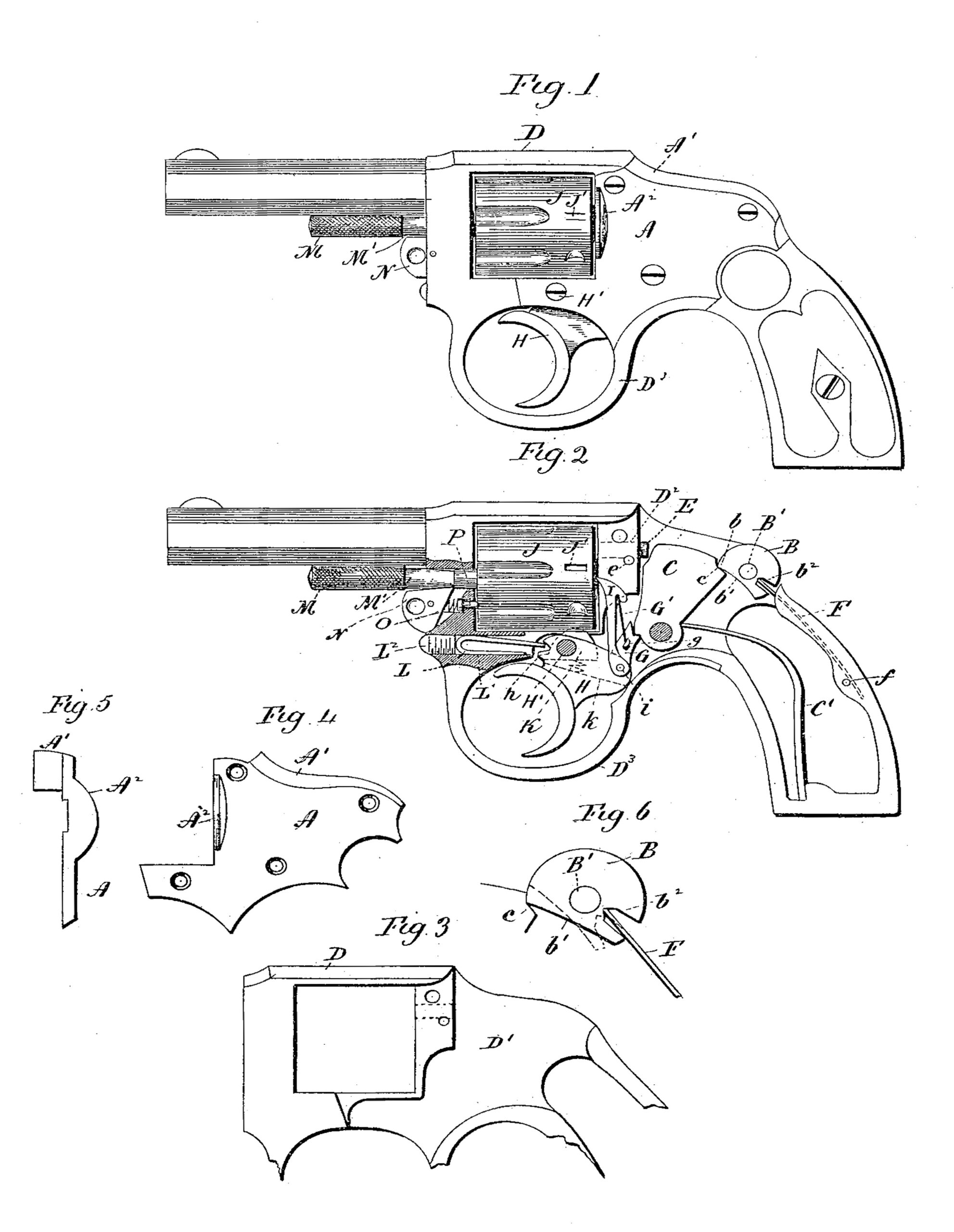
Figure 1, a view in side elevation of a revolver constructed in accordance with my invention; Fig. 2, a view thereof with the cap or cover removed and showing parts of the frame in section; Fig. 3, a broken view of the bare frame; Fig. 4, a detached view of the cap or cover of the frame; Fig. 5, a rear view thereof in end elevation; Fig. 6, an enlarged view of the safety-lock and the spring which operates the same, showing the lock in its locked position by full lines and in its unlocked position by broken lines.
My invention relates to an improvement in concealed-hammer revolvers, the object being to produce a simple, compact and effective arm, not liable to derangement, and constructed with particular reference to facility and cheapness of manufacture and convenience of assemblance.
With these ends in view, my invention consists in a revolver having certain details of construction and combinations of parts as will be hereinafter described and pointed out in the claims.
In carrying out my invention, I construct the plate or cap A of the arm with a flange A’, extending inward from its upper edge, and closing in that part of the frame lying directly forward of the safety-lock B, and directly over the concealed hammer C. By forming the said flange integral with the cap, I greatly facilitate and cheapen the manufacture of the arm over the prior construction in which a corresponding flange is formed integral with the frame D of the arm, and interferes with the free use of machine-tools in milling out the frame to receive the feeding and firing mechanism of the arm.
It will be readily seen by inspection of Fig. 3 of the drawings that under my invention the diagonal chamber D’ in the frame is open at both ends, and readily admits milling or other tools. By leaving this flange off from the frame, and forming it integral with the plate or cap A, I am also enabled to get into the frame readily for boring the socket D2 receiving the firing-pin E, the reciprocation of which is limited by means of the pin e.
I am aware that it has been proposed heretofore to secure the advantages of my invention by making the flange A’ independent of the frame and cap in which case it has had the form of a very small plate, but that construction is objectionable, as it forms a separate part which must be very nicely fitted, and which is not convenient to secure in place. Under my invention also, I form one of the recoil shields A2 integral with the forward edge of the cap or cover A, as clearly shown in Figs. 1, 4 and. 5. Heretofore, this shield has been formed integral with the frame of the arm, making the construction of the frame more difficult. The corresponding recoil shield on the opposite side of the arm is not shown, but it may be said that it is formed in the usual manner, integral with the frame. I thus facilitate and cheapen the construction of the arm by forming the flange A’ and the recoil-shield A2 integral with the cap or cover A of the frame, whereas in prior constructions the shield has been formed integral with the frame itself, and the flange either integral with the frame, or in the form of a small plate made independent of and secured thereto.
The safety lock B of my improved device projects slightly above the surface of the frame and cap, and has a roughened periphery, which is engaged by the fingers for turning it on its horizontal pin B’. The forward end of this lock is constructed with a nose b, which takes into a locking notch c formed in the rear upper corner of the concealed hammer C, the inner edge of the lock being cut away, as at b’ to permit the hammer to be thrown back under it into its cocked position.
In the rear portion of the lock I form a transverse radial notch b2, having substantially parallel upper and lower walls, which at their inner ends converge and intersect. This notch receives the forward end of a flat sheet metal spring F, located within a groove formed in the frame, and secured in place by a pin f. The slot b2 just mentioned is radial with respect to the pin B’ on which the safety-lock B turns, and when the lock is in a position intermediate between its unlocked and locked position, the center of the notch and the center of the pin B’ are substantially intersected by the plane of the spring F. When therefore, the lock is moved into its locked or unlocked position, the spring, the forward end of which engages with the intersecting converging walls of the notch, will be thrown to one side or the other, as may be, of the center of the pin, whereby the lock is held in its open or closed position by a single spring, which for that purpose is moved to opposite sides of the center on which it turns. This construction is very simple and effective. I need not further refer to the hammer C, more than to say it is operated in being thrown into its firing position by a heavy spring C’, and is lifted back against the force of the said spring into its cocked position, and there held by means of a sear G, pivotally mounted in the rear end of the trigger H, which is hung at its forward end on a pin H’.
The sear is provided with a pin g’, which is engaged by the lower end of a spring G’, the upper end of which is secured to the rear edge of the operating-pawl I, which engages with a circularly arranged series of ratchet teeth j, formed in the usual manner upon the rear end of the cylinder J, which is intermittently rotated by means of the said pawl, the lower end of which is pivotally connected with the rear end of the trigger by means of a pin i on which the sear is also mounted.
A locking dog K, mounted in the forward end of the trigger, enters locking notches J’ formed in the periphery of the rear end of the cylinder, which is locked in its several firing positions by the said dog, the same being lifted into the said notches by means of a small spiral spring k.
The forward end of the trigger is constructed with a notch h, designed to receive one end of the trigger spring L, which is located in a chamber L’ open at both ends, formed in the base of the trigger-guard D3, which in fact constitutes a part of the frame D. Instead of boring an opening from the inside of the guard forward to receive this spring, I begin at the forward end of the base of the guard, and bore rearward into the chamber D’ of the frame. I then insert the trigger spring into this opening, and hold the same therein by means of a screw-plug L. This provision for the trigger spring is inexpensive and convenient, and enables the spring to be removed and replaced at pleasure without disturbing any other part of the arm.
The removable pin M on which the cylinder J is mounted, is held in place for the support of the said cylinder by means of a retaining dog N, which enters a wide circumferential recess M’, formed in the pin, as seen in Fig. 2. The said dog is held in its operating position by means of a small’ spiral spring O, which under my invention has the additional function of holding the friction pin P up to its work, the said pin being mounted in the frame D, and arranged to engage with the forward end of the cylinder, and prevent the same from retrograde rotary movement under the action of the pawl I, when the same is being drawn over the ratchet-teeth J preparatory to being successively engaged with them for the rotation of the cylinder. Under the construction last mentioned I make the spring O, perform the two-fold function of operating the retaining-dog N and the friction pin P, whereby simplicity of construction and fewness of parts result.
It is obvious that in carrying out my invention some changes from the particular construction herein shown and described may be made, and I would therefore have it understood that I do not limit myself to the particular construction herein shown and described, but hold myself at liberty to make such changes as fairly fall within the spirit of my invention.
Having fully described my invention, what I claim as new, and desire to secure by Letters Patent, is—
1. The combination with the frame and the other instrumentalities of a revolver, of a cap or cover fitted to the said frame, and constructed upon its forward edge with a recoil-shield, substantially as described.
2. The combination with the frame and the other instrumentalities of a revolver, of a cap or cover fitted to the said frame, and provided upon its upper edge with an inwardly projecting flange, and upon its forward edge with a recoil-shield, the said flange and shield being formed integral with the cap or cover substantially as described.
3. In a revolver, the combination with a frame having a spring-chamber formed in the base of its trigger-guard and open at both ends, of a trigger, a trigger spring located in the said chamber in front of the trigger, and engaging at its rear end therewith, and a screw-plug located in the forward end of the said chamber for holding the trigger-spring in place therein, substantially as described.
4. In a revolver, the combination with the cylinder, of a cylinder pin constructed with a circumferential recess, a retaining-dog entering the said recess for holding the pin in position, a friction pin mounted in the frame, and arranged to engage with the forward end of the cylinder for preventing the rotary retrograde movement thereof, and a spring engaging with the said pin and dog, and compelling both to perform their functions, substantially as set forth.
In testimony whereof I have signed this specification in the presence of two subscribing witnesses.
JOHN T. SMITH.
Witnesses:
ERNEST D. BRICK,
GEORGE A. LEONARD.