
US 530759
UNITED STATES PATENT OFFICE.
CHARLES FOEHL, OF PHILADELPHIA, PENNSYLVANIA, ASSIGNOR OF ONE-HALF TO HENRY RUHLAND, OF SAME PLACE.
REVOLVER.
SPECIFICATION forming part of Letters Patent No. 530,759, dated December 11, 1894.
Application filed January 8, 1894. Serial No. 498,487. (No model.)
To all whom it may concern:
Be it known that I, CHARLES FOEHL, a citizen of the United States, residing in the city and county of Philadelphia, State of Pennsylvania, have invented a new and useful Improvement in Firearms, which improvement is fully set forth in the following specification and accompanying drawings.
My invention consists of a pistol or other fire-arm which is provided with means for retaining the revolving chamber or cylinder in operative position, the same being readily manipulated, so as to permit the removal of the same.
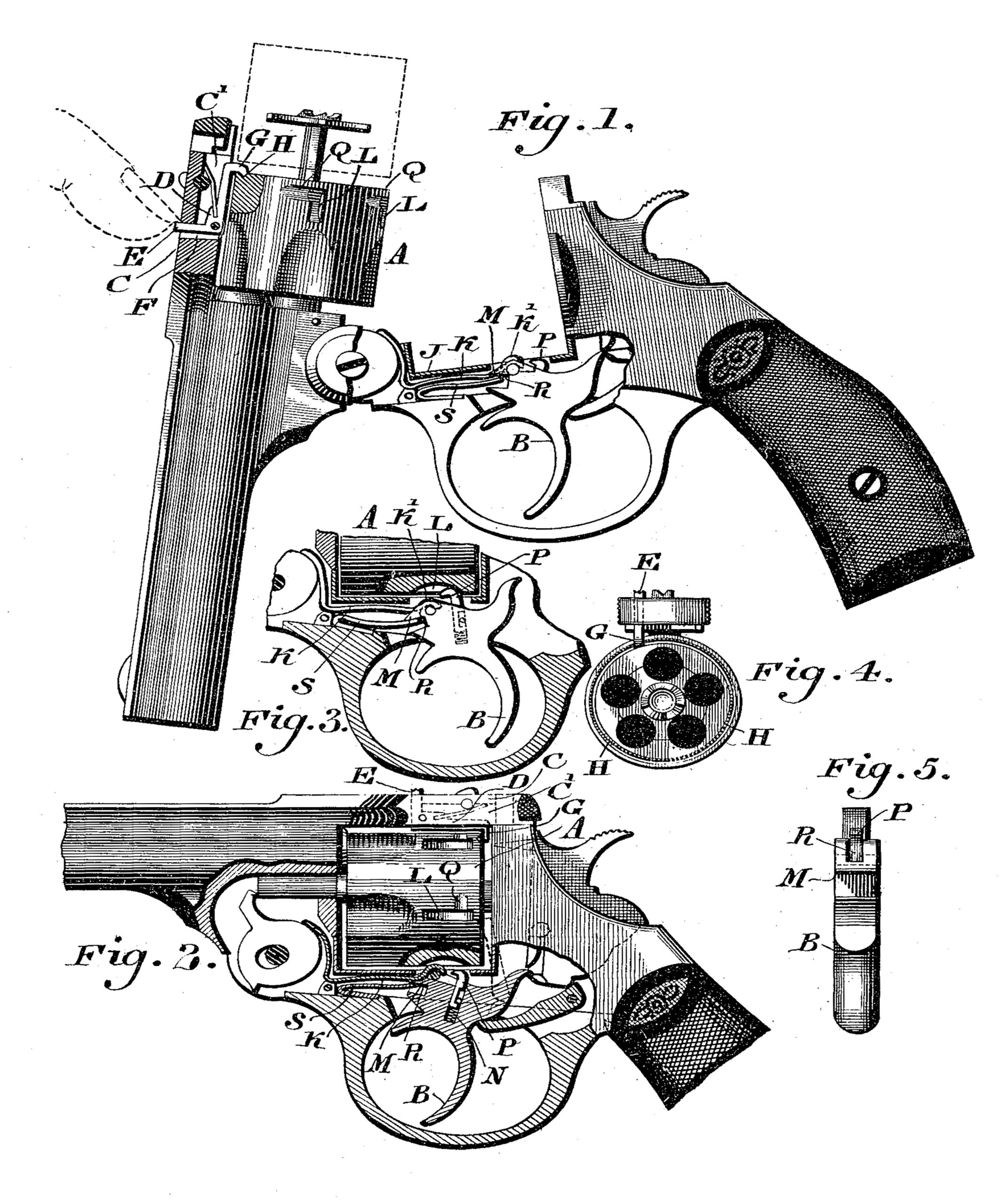
Figure 1 represents a side elevation partly broken away of a pistol embodying my invention, the muzzle being depressed. Fig. 2 represents a partial side elevation and partial longitudinal section of a portion of the pistol, the muzzle being elevated. Fig. 3 represents a section of a portion. Fig. 4 represents an end view of the cylinder and connected portions. Fig. 5 represents an end view of the trigger.
Similar letters of reference indicate corresponding parts in the several figures.
Referring to the drawings: A designates the rotary chamber, and B the trigger of a pistol, which parts, excepting the features of my invention applied thereto are of usual construction. In the strap C, which is above the barrel, there is a chamber C’, in which is located the spring-actuated catch D of angular form, the same having the limb E protruding through the opening F in said strap. The nose G which is on the other limb of said catch is adapted to freely engage with the rear end of the chamber A, in a circular or annular recess H therein, so that while said chamber is permitted to rotate, it is prevented from rearward displacement, owing to the locking action of said nose G When the limb E is properly depressed, the nose. G moves away from the end of the chamber, beyond the periphery thereof, and thus the chamber may be withdrawn, as shown in dotted lines for any purpose required. When the chamber is restored to position, the nose G again engages with the chamber and controls the longitudinal motion of the same.
Connected with the frame J, below the chamber A, is a spring catch K, whose head K’ is adapted to enter a portion of either recess L in the chamber A, the portion of said catch, near the head thereof, resting on the lip M, at the forward part of the trigger so as to be raised by the same, the tendency of said catch being to lower, which it does when the trigger is pulled. In the trigger is a vertical recess N, which is occupied by the shank of a spring-pressed bolt or catch P, whose head is adapted to enter a portion of either recess L in the chamber when the trigger is pulled, as will be hereinafter explained.
In the chamber are recesses Q, which extend around the same at a right angle to the recesses L, so that when the catch P rises and the chamber rotates, the head of the former enters the approaching recess Q, and is thus properly guided into the recess L.
In order to seat the head of the catch K on the lip M, and prevent lateral motions thereof, said lip is formed with a recess R to receive said head, as most clearly shown in Figs. 3 and 5. It will be seen that when the trigger is in its normal position, the catch K is elevated by the lip M of the trigger. Consequently the head K’ of said catch occupies a portion of the adjacent recess L, and thereby locks the chamber and prevents rotation of the same. As the rear portion of the trigger is lowered, as most plainly shown in Fig. 2, the catch P is removed from said recess, and is thereby rendered inoperative. When however the pistol is to be discharged, and the trigger is drawn back, the lip M is lowered, and the catch K owing to its springy nature, lowers and causes its head to withdraw from the recess L, whereby the chamber is unlocked. The chamber rotates as usual, and as the rear end of the trigger rises, the catch P is raised and it contacts yieldingly with the periphery of the chamber, and then enters the recess Q, which has advanced toward it, after which it drops into the portion of the recess, L, which communicates with the said recess Q, whereby the chamber is locked by said catch P, this occurring just in advance of the firing or discharge of the pistol, and continuing until the firing is accomplished. See Fig. 3. The trigger now returns to its first position, whereby the catch P is lowered, and the chamber is unlocked, but as the lip M rises, due to the returning motion of the trigger, the head K’ is forced into the adjacent recess L, thus again locking the chamber and preventing rotation of the same, while being carried or handled until the trigger is drawn back, when the operations hereinbefore described are repeated. It will be observed that the trigger is provided with a spring S which bears against the same and the frame, for raising the forward end of the trigger and restoring it to its normal position after firing.
It will be seen that during the operation of extracting the empty cartridge shell, the chamber A is controlled by the catch D, and thus retained in position without being disturbed by the action of the extractor.
Having thus described my invention, what I claim as new, and desire to secure by Letters Patent, is—
1. A fire arm having a rotary chamber with an annular recess in the rear end thereof, and a movable catch having one end freely entering said recess and adapted to be withdrawn therefrom, substantially as described.
2. A fire arm having a rotary chamber with an annular recess in the rear end thereof, a strap with a chamber therein, and a spring-actuated catch in said chamber, one limb of said catch occupying an opening in said strap, and the other limb freely engaging the end of the rotary chamber in said annular recess, substantially as described.
CHARLES FOEHL.
Witnesses:
JOHN A. WIEDERSHEIM,
A. P. JENNINGS.