
Britain 2579
A.D. 1875, 20th July. № 2579.
Revolving Cylinder Pistol.
LETTERS PATENT to William Robert Lake, of the Firm of Haseltine, Lake, & Co., Patent Agents, Southampton Buildings, London, for the Invention of “An Improved Revolving Cylinder Pistol.”— A communication from abroad by E. Remington & Sons, of Ilion, New York, United States of America.
Sealed the 18th January 1876, and dated the 20th July 1875.
PROVISIONAL SPECIFICATION left by the said William Robert Lake at the Office of the Commissioners of Patents, with his Petition, on the 20th July 1875.
I, William Robert Lake, of the Firm of Haseltine, Lake, & Co.,
Patent Agents, Southampton Buildings, London, do hereby declare the nature of the said Invention for “An Improved Revolving Cylinder Pistol,” a communication, to be as follows:—
My Invention relates to pistols of that class which have a chambered revolving cylinder at the rear of the barrel, and the said Invention consists in a novel construction and arrangement of parts in combination with the said cylinder, whereby the extractor for removing the empty or discharged cartridge shells from the chambers in the same is fitted to the barrel in a more compact, convenient, and sightly manner than heretofore.
In common with other arms of this class my improved pistol has its revolving cylinder fitted to turn upon a centre rod, which extends forward from the breech within a hole or chamber, formed inside the portion of the frame below the barrel. This rod is removable so that it can be withdrawn to liberate the cylinder to permit the latter to be removed from the arm when required.
The extractor commonly used for these pistols is a rod fitted in a tube at the side of the barrel, in such a position that as each chamber of the cylinder is turned away from the barrel it comes in line with the said extractor, and then by force exerted upon the latter the cartridge shell is pushed back and out of the cylinder. But by this Invention I avoid the clumsy, heavy, and unsightly appearance given to the arm by the aforesaid tube, as will be understood by the following description:— In the side of the metal piece which encloses the centre rod I form a groove or channel, and from this channel a narrow aperture or slot extends into the cavity in which the said centre rod is fitted.
In the aforesaid groove or channel at the side of the metal frame I fit the extractor which is a round rod of suitable size. This extracting rod has at its forward end a head which projects outside of the groove and forms the means whereby the said rod is pressed back in extracting the cartridges; and from this head extends inwardly an arm whose extremity encircles the centre rod and slides freely on the same. The hole or cavity wherein the said centre rod is enclosed has its bore larger than the diameter of the said rod, to permit the arrangement therein of a spiral spring which is placed around the said centre rod. One end of the said spring abuts against the metal frame at the rear of the said hole or cavity, while the other end of the said spring presses against the arm on the extractor rod and forces the same forward, thereby keeping the extractor clear of the chambers in the cylinder, but allowing the same to be freely forced down or inward in the act of extraction The said centre rod is provided at its forward end with a small spring catch, which holds the said centre rod securely in place, but which is easily depressed to allow the said centre rod to be drawn out to liberate the cylinder when required.
The part of the frame in which the centre rod and extractor are fitted adds very little to the weight of the arm, and has a neat and compact form; it is attached to the barrel by a screw at its forward end and held on the breech strap by a pin projecting from the same, and may be removed by taking out the said screw. And the centre rod and extractor and its spring may be very quickly removed and replaced when worn or injured.
SPECIFICATION in pursuance of the conditions of the Letters Patent, filed by the said William Robert Lake in the Great Seal Patent Office on the 19th January 1876.
TO ALL TO WHOM THESE PRESENTS SHALL COME, I, William Robert Lake, of the Firm of Haseltine, Lake, & Co., Patent Agents, Southampton Buildings, London, send greeting.
WHEREAS Her most Excellent Majesty Queen Victoria, by Her Letters Patent, bearing date the Twentieth day of July, in the year of our Lord One thousand eight hundred and seventy-five, in the thirty-ninth year of Her reign, did, for Herself, Her heirs and successors, give and grant unto me, the said William Robert Lake, Her special licence that I, the said William Robert Lake, my executors, administrators, and assigns, or such others as I, the said William Robert Lake, my executors, administrators, and assigns, should at any time agree with, and no others, from time to time and at all times thereafter during the term therein expressed, should and lawfully might make, use, exercise, and vend, within the United Kingdom of Great Britain and Ireland, the Channel Islands, and Isle of Man, an Invention for “An Improved Revolving Cylinder Pistol,” a communication to me from abroad by E. Remington and Sons, of Ilion, New York, United States of America, upon the condition (amongst others) that I, the said William Robert Lake, my executors or administrators, by an instrument in writing under my, or their, or one of their hands and seals, should particularly describe and ascertain the nature of the said Invention, and in what manner the same was to be performed, and cause the same to be filed in the Great Seal Patent Office within six calendar months next and immediately after the date of the said Letters Patent.
NOW KNOW YE, that I, the said William Robert Lake, do hereby declare the nature of the said Invention, and in what manner the same is to be performed, to be particularly described and ascertained in and by the following statement, reference being had to the accompanying Drawing forming a part of this Specification:—
My Invention relates to pistols of that class which have a chambered revolving cylinder at the rear of the barrel, and the said Invention consists in a novel construction and arrangement of parts in combination with the said cylinder, whereby the extractor for removing the empty or discharged cartridge shells from the chambers in the same is fitted to the barrel in a more compact, convenient, and sightly manner than heretofore.
In common with other arms of this class my improved pistol has its revolving cylinder fitted to turn upon a centre rod, which extends forward from the breech within a hole or chamber formed inside the portion of the frame below the barrel. This rod is removable so that it can be withdrawn to liberate the cylinder to permit the latter to be removed from the arm when required.
The extractor commonly used for these pistols is a rod fitted in a tube at the side of the barrel, in such a position that as each chamber of the cylinder is turned away from the barrel it comes in line with the said extractor, and then by force exerted upon the latter the cartridge shell is pushed back and out of the cylinder. But by this Invention I avoid the clumsy, heavy, and unsightly appearance given to the arm by the aforesaid tube, and render the arm more generally efficient and convenient, as will be understood by the following description:—
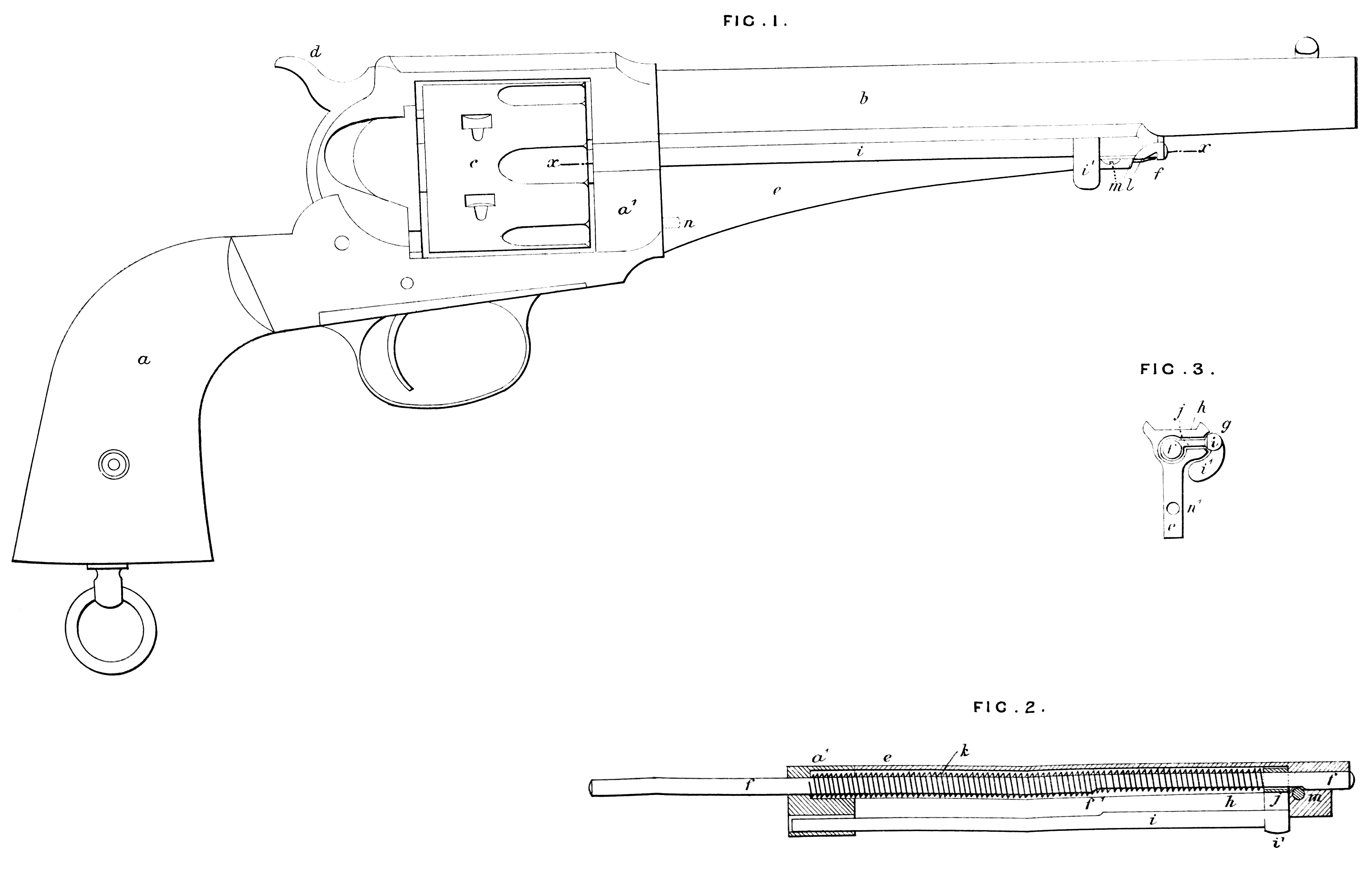
In the accompanying Drawing Figure 1 is an exterior side view of a pistol constructed according to this Invention; Figure 2 is a longitudinal section of portions of the said pistol on the line x, x, Figure 1, shewing the extractor and parts connected therewith; Figure 3 is a rear end view of the extractor, centre rod, and detachable frame.
Like letters indicate the same parts throughout the Drawing.
The stock a, barrel b, and revolving cylinder c are constructed as heretofore, and the usual mechanism is provided for actuating the said cylinder and the cock or hammer d.
In the side of the metal piece or frame e which encloses the centre rod f, I form a groove or channel g, which opens through a long narrow aperture or slot h into the hole in which the said centre rod f is fitted.
In the aforesaid groove or channel g at the side of the metal frame e I fit the extractor i, which is a round rod of suitable size, as shown. This extractor or extracting rod i has at its forward end a head or knob s¹ which projects outside of the groove, and forms the means whereby the said rod is pressed back in extracting the cartridges; from this head i¹ extends inwardly an arm j whose extremity encircles the centre rod f, and slides freely endwise on the same. The hole or cavity wherein the said centre rod is enclosed has its bore larger than the diameter of the said rod to permit the movement of the said arm, and the arrangement therein of a spiral spring k which is coiled around the said centre rod f. One end of the said spring abuts against the rear end of the hole or cavity in the breech strap a¹, while the other end of the said spring presses against the arm j on the extractor rod i, and presses the same forward, thereby tending to keep the extractor clear of the chambers in the cylinder c, but allowing the said extractor to be freely forced down or inward in the act of extraction of the cartridge shells. The said centre rod is provided at its forward end with a small spring catch 7 which holds the said centre rod f securely in place, but which by its depression, which is easily and conveniently effected, allows the said centre rod to be drawn out to liberate the cylinder c when required.
The peculiarly constructed frame e in which the centre rod and extractor are fitted adds very little to the weight of the arm, and has a neat and compact form. It is attached to the barrel b by a screw m at its forward end, and held on the breech strap a¹ by a pin n projecting from the latter into the hole n¹, and may be liberated to permit it to be removed from the arm by taking out the screw m. And the centre rod and extractor and its spring may be very quickly removed and replaced or renewed when worn or injured, without disturbing or displacing any of the other portions of the pistol. The screw m also serves to keep the rod f in place, the said rod having a flat portion on one side to slide over the said screw and a shoulder at f¹, which forms a stop at the end of the said flat portion.
Having thus fully described the said Invention as communicated to me by my foreign correspondents, and the manner of performing the same, I wish it understood that I claim, in a revolving cylinder pistol the devices comprising the piece or frame e secured detachably or removably on the barrel and breech strap, the extractor or extracting rod fitted to slide in the longitudinal groove or channel which extends into the hole or cavity of the centre rod, the arm on the said extracting rod fitted to slide upon the said centre rod and held back by a spring, and the devices for securing the said piece or frame and retaining the rods securely therein, constructed and combined with the other parts of the pistol for the purpose of rendering the same less clumsy and unsightly in appearance, and more generally efficient and convenient, as herein set forth.
In witness whereof, I, the said William Robert Lake, have hereunto set my hand and seal, this Nineteenth day of January, in the year of our Lord One thousand eight hundred and seventy-six.
Wᵐ. Rᵀ. LAKE (L.S)
Witness,
Jaˢ. Edwards,
8, Southampton Buildings,
London.