
US 10259
UNITED STATES PATENT OFFICE.
MORGAN L. ROOD, OF MARSHALL, MICHIGAN.
IMPROVEMENT IN REVOLVING FIRE-ARMS.
Specification forming part of Letters Patent No. 10,259, dated November 22, 1853.
To all whom it may concern:
Beit known that I, Morgan L. Rood, of the town of Marshall, in the county of Calhoun and State of Michigan, have invented a new and useful Improvement on a Revolving Rifle; and I do hereby declare that the following is a full, clear, and exact description of the construction and operation of the same, reference being had to the annexed drawings, making a part of this specification, in which—
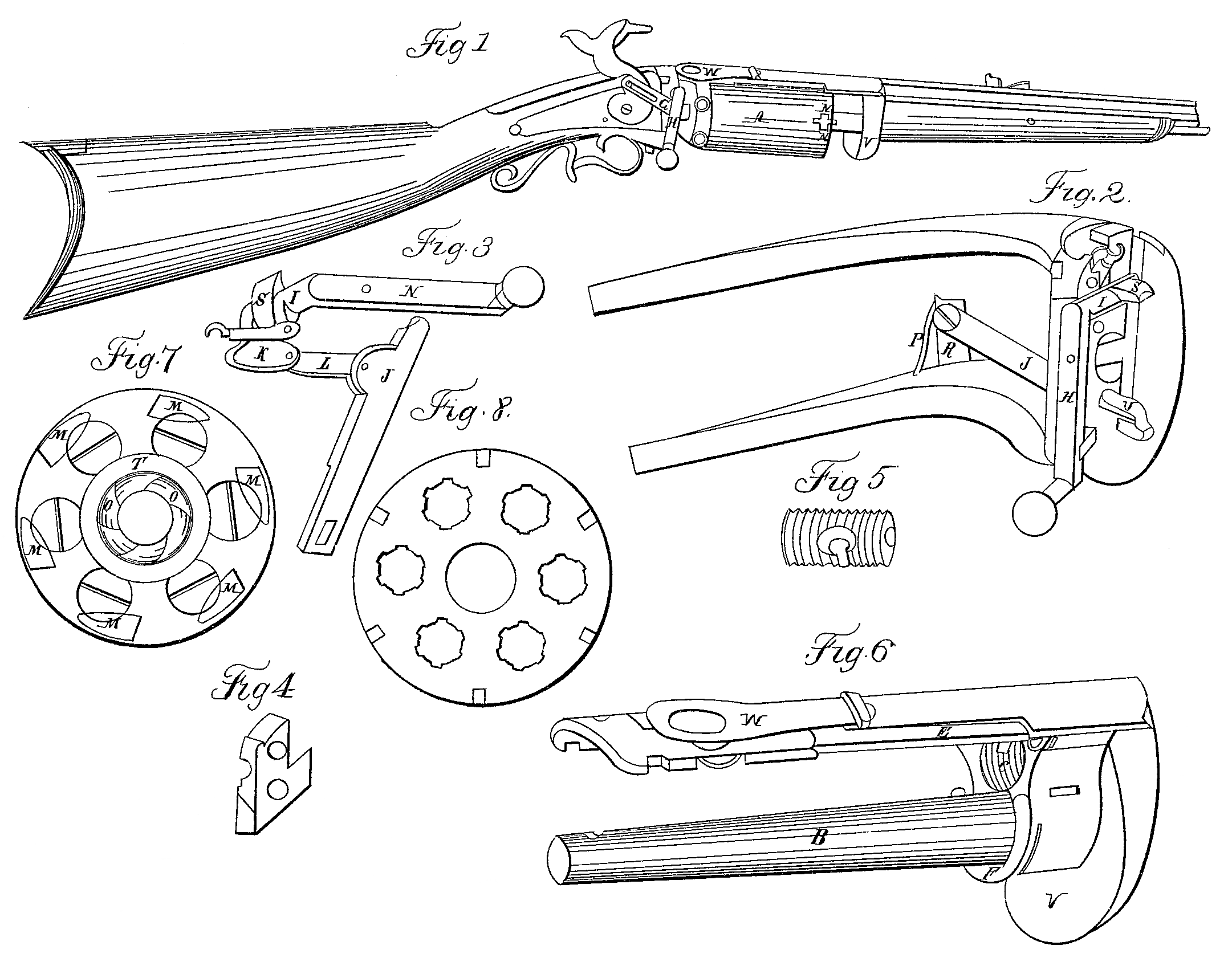
Figure 1 is a side perspective view of the rifle, showing only a part of the barrel; Fig. 2, the breech-plate with the revolving gear, &c., attached; Fig. 3, the same gear (detached) for revolving and tightening the cylinder, &c., consisting of a rock-shaft, crank-arm, cam, lever, stirrup, tumbler, and hook-connection; Fig. 4, the cap-plate and rock-shaft; Fig.5, the breech-pin; Fig. 6, the mandrel, guard, and cap-plate in one piece; Figs. 7 and 8, end views of revolving cylinder.
The same letters refer to like parts.
My revolving cylinder A, Fig. 1, is pierced with a hole in the center slightly tapered, so that When the end is in contact with the barrel it will accurately fit the taper mandrel B, Fig. 6.
The barrel is finished in the usual manner and firmly screwed in the hole C, Fig. 6, and the end of the barrel and cylinder ground to a perfect joint.
The cylinder is slightly chamfered where the cones for the percussion-caps are inserted, and at the other end has guiding and stop notches or grooves to guide and hold it to its place. These grooves fit into the guide-pin D, Fig. 6, when the cylinder is close up to the barrel, they being guided opposite to the pin by the adjusting-spring E dropping into the sloped notches N N, Fig. 1, the spiral spring F throwing back the cylinder while revolving. The guide-pin and spiral spring are both made to detach for the purpose of grinding the cylinder and barrel to a joint. The cylinder is bored and grooved or rifled through and through, it being put on its own mandrel for that purpose, with the barrel attached so that the bores and grooves may correspond exactly.
The breech-pins, Fig. 5, are screwed into the end of the cylinder and countersunk flush, as seen in Fig. 7. I usually make my breech-pins seven-eighths of an inch long, thus giving room for the cones, which are screwed into them through the cylinder and countersunk below its periphery.
There is a hole through the breech-plate to receive the end of the mandrel, and also suitable slots and recesses for the revolving gear, the upper part being also grooved to receive and lock the end of the cap-plate of the mandrel-piece, when the whole is firmly secured by a Screw-bolt passing through.
My mode of cocking this gun, revolving the cylinder, and making a close joint with the barrel is as follows: The revolving gear being in the position as shown in Figs. 2 and 3 and the hammer down, it is cocked by the same motion that revolves the cylinder by means of the slotted arm G, Fig.1, being in connection with the revolving crank arm H and the hammer. This crank, being pulled in a direction to cock, revolves the rock-shaft I and raises the lever J by means of the tumbler K and connecting-stirrup L, Figs, 2 and 3. This lever acts upon teeth O O, Fig. 7, cut in the end of the cylinder and chamfered on the outside, causing the cylinder to revolve until it is stopped by the spring E slip ping into the sloped notches N N and the forward projection of the tumbler K catching in the grooved notches MM, Fig. 7, in the end of the cylinder. The revolving lever J is pressed against the teeth on the end of the cylinder by a spring, P, Fig. 2, where it is attached to the standard R by a screw through a slot. The cylinder having been revolved and the gun put on the full-cock, the crank H is brought back to its former position. This elevates the cam S, which is formed on the rock-shaft, bringing it in line with the cylinder and pressing it against the barrel and making it tight and firm, having been brought precisely to its place by the guide-pin and notches. This cam, in the act of revolving, drops into the circular groove T, Fig. 7, while the cylinder recedes and turns, it being kept at its proper distance from the breech-plate by a stud, U, Fig. 2, which also works in this groove and is kept in contact by the spiral spring.
The guard W, Figs. 1 and 6, is for additional safety in case of any accidental discharge. I also use a smoke-guard, W, Figs. 1 and 6, for the purpose of keeping the revolving gear clean and protecting the surrounding charges from taking fire. This guard has a short conical tube, through which the hammer plays, and is made to fit tight in a circular groove round the cone or countersink for it. The guard is connected to the cap-plate by a loop, so as to give it free motion longitudinally, and is operated by a short arm on the rock-shaft, to which it is hooked, as shown in Fig. 3, with the hook attached, so that the act of pushing forward the crank H (in order to elevate the cam S and push forward the cylinder to make a close joint with the barrel) depresses the short arm and hook, thereby bringing the tube down to its seat and compelling the fire and smoke from the ignition of the cap to ascend. It is of course raised from its seat by the reverse or cocking motion.
The mandrel is drilled for the reception of the ramrod deep enough to allow the necessary length to load with.
I do not claim the revolving cylinder, nor do I claim as my invention the crank E, rock-shaft I, tightening-cam S, tumbler K, stirrup L, revolving lever I, or spiral spring F, nor the ratchet-teeth O, nor the circular groove T on the end of the cylinder, nor the adjusting spring E, nor the guard V, or their equivalents, they having been before used; nor do I claim a slotted arm, G, as merely connecting the hammer with the crank H; nor do I claim the smoke-guard W; but
What I do claim as my invention, and desire to secure by Letters Patent, is—
1. The peculiar arrangement in fire-arms described above, by which the guide-pin D, Fig. 6, in connection with the stop-notches N N, Fig. 1, adjusting-spring E, and the hook-connection between the smoke-guard W and rock-shaft I, causes a more perfect joint and more secure connection between the cylinder and barrel, thus preventing all leakage, keeping the cylinder and its attachments clean, and protecting the surrounding charges from talking fire.
2. The arrangement of the slotted arm G and the hammer, by means of which the gun may be cocked with or without moving the cylinder.
MORGAN L. ROOD.
Witnesses:
George Johnson,
Isaac Gifford.