
Patent 14420
UNITED STATES PATENT OFFICE.
WM. MT. STORM, OF NEW YORK, N.Y.
IMPROVEMENT IN REVOLVING FIRE-ARMS.
Specification forming part of Letters Patent No. 14,420, dated March 11, 1854.
To all whom it may concern:
Be it known that I, Wm. Mt. Storm, of the city and State of New York, have invented certain new and valuable Improvements in Many-Chambered Fire-Arms, of which this schedule and accompanying drawings constitute a full specification.
The general object of my improvements is to make a revolver more ready and more durable, both of operation and of construction, including repair, combined with elegance and compactness of form, while the more special object has been to provide for greater convenience, quickness, and certainty in the operations of loading and discharging under the comparatively difficult and hitherto neglected contingencies of being in action on horseback or in a boat; also, to render impossible the usual fouling by smoke, &c.
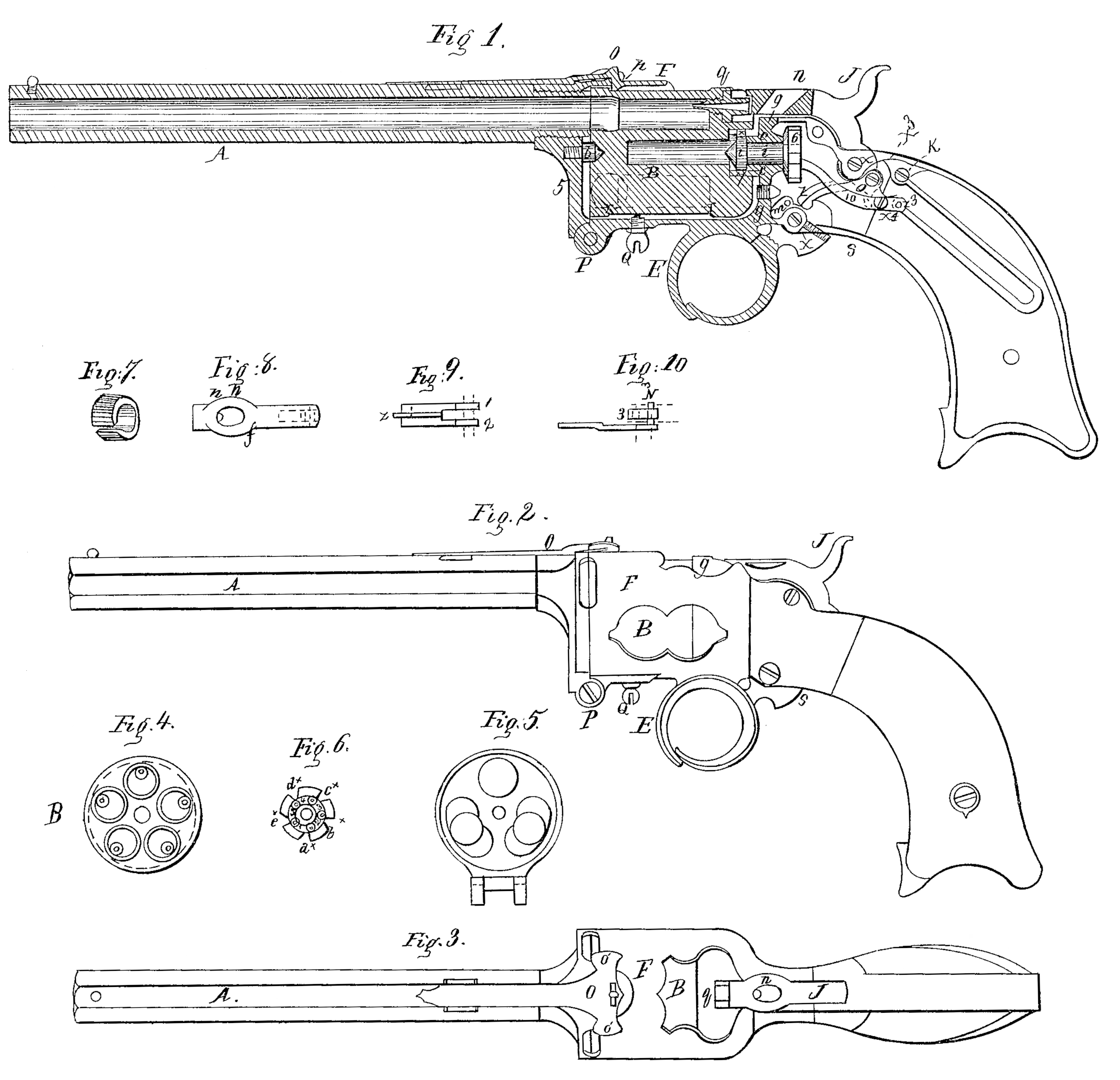
Figure 1 is a section; Fig. 2, a side elevation; Fig. 3, an exterior top view; Fig. 4, a muzzle view of chambered cylinder; Fig. 5, an interior face view or elevation of apron-piece, in which is carried and supported the barrel and the front center on which the cylinder turns. Fig. 6 is a full face view of the revolving and locking wheel hereinafter described. Fig. 7 is the bush-ring belonging in the rear of the cylinder, and whose character is herein after specified. Fig. 8 is a top or plan view of the hammer; Fig. 9, a similar view of the dog; Fig. 10, the same of the revolving pawl.
A is the barrel; B, the cylinder, whose front end turns on the center point, b. The bush-ring, Fig. 7, and 7, Fig. 1, being driven down to a shoulder in the breech of the shoulder, but projecting a little beyond it, receives the recoil of discharge. It also projects over the short sleeve C, projecting from the solid stock, which is a single casting from the hinge P to the extremity of the handle, including the guard E and cask F. C. constitutes the rear center on which the cylinder turns.
Behind the recoil-shield g is the revolving and locking wheel 6, fixed on the revolving shaft i, which has at the opposite end-the button-head i’ of the size of c, and both projecting into and fitting the bush-ring 7. The joint between if and c is thus covered, and beyond the fire of the cap, so that no smoke can find its way (even if the shaft i were not, as it is, close fitting) into the lock to foul it, an almost or quite universal evil in revolvers. The taper headed screw x in i’ slides snugly but freely into the slot in 7, and thus when the said button, shaft, and wheel 6 revolve, the cylinder is forced with them.
I is the hammer; X”, its fulcrum, below which its heel projects, and in which, at X^3, is hung the dog 9, the jaws 1 and 2 of which (see Fig. 9) span said heel of the hammer. These jaws also project downward, and receive between them the jaw 3 of the pawl, Fig. 10, the whole being connected by screw X^4, as a fulcrum to the pawl. Thus, as seen, the hammer, pawl, dog, and trigger are all simple levers of the first order. X^v is the fulcrum of the trigger.
In the face of wheel 6 are five circular conical indentations, 1 2 3 4 5, in purpose the equivalents of so many teeth of an ordinary ratchet. On the edge of this wheel are as many notches, a^x, b^x, c^x, d^x, and e^x. By these the cylinder is surely stopped from revolving too far, and then locked in place.
The operation is as follows: When the trigger is pulled its top (a segment of an eccentric) moves forward, pulling with it the dog, the hook on the forward end of which catches over or into a shoulder or notch in the head of the trigger, as seen, and the nose of the dog is so, as will be understood, carried upward as well as forward. The point of the pawl resting in one of the indentations in the face of wheel 6, forces the latter at the same time to revolve. Projecting from the top of the head of the dog is the flange or crest Z of the same thickness as the bottom of the notches in the edge of wheel 6. Now, the simultaneous rotation of 6 and the forward and upward movement of the crest Z bring the side of the latter at the proper moment against the steeper and higher side of the locking-notch in the edge of 6, and rotation of the cylinder is stopped, while at the same instant the under surface of the forward end of Z is borne on the conical projecting point of an adjustable tripping-screw, Z’, and any further pull of the trigger forces the top of Z into the bottom of the locking-notch, whereon the hook of the dog is freed from the trigger, when the hammer would fall and the discharge take place; but as a weapon going off, as would then be the case, does not permit a deliberate aim, owing to the uncertainty to the operator of the instant the hammer is to fall, I provide another notch or shoulder (a screw is best) on the rear of the head of the trigger at S, upon which a projection on the bottom of the hammer (shown in Fig. 1 by red dotted lines) catches at the instant the forward notch on the trigger releases the projection or hook of the dog, so that while the trigger is held firmly back in its then position the hammer remains cocked; but if the trigger is the least slackened forward, the tooth on the hammer is released from it and the discharge takes place. Thus the instant of discharge is both known and controlled, and deliberate aim allowed.
The mainspring in my weapon in itself performs all the duties derived from several springs in more usual forms of construction. It has at one of its extremities the usual bifurcated hook, which hooks under the pin Z^3 of the pawl, Fig. 10. On distension it will, as will be clear, press down the forward end of the pawl, preventing it from slipping from the revolving indentations, and through the pawl bear down the forward end of the dog on the trigger and through the dog bear down the head of the hammer on the cones—the latter being the only usual duty of a mainspring. After discharge, the downward pressure of the hook of the dog upon the then steeply-inclined and eccentric top of the trigger forces (as the finger relaxes the pull) the latter back into the position shown in Fig. I, and causes the parts to take the proper arrangement for another discharge by another pull, &c. If the stationary end of the mainspring was also a fixed end, a link would be necessary to connect its opposite end with the pawl as both vibrate. To save this the stationary end is perforated and swiveled on a pin or screw, K, and between a couple of lugs or jaws projecting from the stock. The spring is thus enabled in itself to perform the duties of a link in a manner readily understood.
The pin in in the head of the trigger, by striking the bottom of the recess in front of it, prevents the occurrence of a jerk by the sudden jumping farther of the trigger when the resistance to the pull of the finger, by the tension of the mainspring when the parts detach to allow the fall of the hammer, ceases.
Through the head of the hammer is a hole, 7, which, when the hammer is at full-cock, comes horizontally in the line of sight and aids in taking aim. I employ, however, in addition a spring-back-crotch sight very similar to those of ordinary hunting-rifles. This sight or spring (marked O) serves, in a manner presently understood, to lock the barrel and cylinder together after loading and in place for firing. This spring, which is fastened to the barrel by the usual block and dovetail, has at its rear end a heavy lip or hook, p, which hooks into a corresponding opening in the “casque” F, which latter surrounds and protects the cylinder, extending as far forward as the face of the latter, and forms a holder or receptacle for it while being loaded, offering a very great convenience. To the casque, by the hinge P, is joined the apron-piece, (see Fig. 5,) which, together with the barrel and center b, is turned down away from the cylinder, leaving the chambers as fully exposed as in Fig. 4for loading. To turn down the apron-piece in this manner, O is seized by the forefinger and thumb under the ears o’, and the lip p is lifted out of the recess, and in the operation the apron-piece thrown forward and turned down out of the way. After loading, seize the barrel, and pressing it up to the horizontal position, the rear of lip p, being beveled, on striking the edge of the casque raises the spring, slides over, and Snaps into its place, the whole operation of locking and unlocking being much like opening or closing a jack-knife.
When the barrel is turned down and the cylinder loaded the latter may be pushed forward in the casque by the thumb a 9 for more easy capping; but to prevent dropping out and losing the cylinder while in motion, as on horseback, or in action or like emergency, there is a circumferential recess turned upon its exterior from r to r’, and into this, but not quite touching, projects the point of the safety screw Q, which is stationary in the casque at a convenient point.
Now the entire withdrawal of the cylinder from the casque cannot be effected without Q being first purposely in part withdrawn. If the weapon be carried in a trunk, for instance, while loaded, the screw Q, by being screwed firmly in against the cylinder, fastens the entire works from operation, thus tending to prevent damage to the weapon or accidental discharge.
The cones have points projecting inward, as seen, their object being to puncture a cartridge when a cartridge is used.
As in a rifle the barrel would be too heavy to hinge and turn down, it could be arranged to load without detaching the cylinder and barrel.
I have anticipated the use of a long trigger arranged to fold up, when not in use, under the weapon; but I prefer the form shown.
Having now fully described my improved revolver, what I claim and desire to secure by Letters Patent, is as follows:
1. Extending the casque forward as far as the face of the cylinder and surrounding it to form a receptacle or holder for it while loading, in combination with a hinged apron-piece, Fig. 5.
2. In combination with the so arranged barrel and casque, and for locking them together, the solid self-acting locking-spring, (as distinguished from a locking-lever having by necessity a hinge to Wear loose, &c.) said spring being arranged to resist in the discharge by its direct tensile strength, as shown.
3. In combination with the casque or cylinder receptacle, the safety-screw Q’, projecting into the recess between the shoulders r r (order from getting dropped while loading or capping in action, as explained.
4. The central revolving shaft with the button-head i’ forward of the sleeve C, and both projecting within the central cavity of the cylinder beyond the line of its rear and the fire of the cap, in combination with a revolving wheel located within the stock, inclosed from the fire and smoke, all substantially as explained and shown.
5. In combination with the dog having an inclined plane or projection at its forward end to meet the purpose of such combination, an adjustable tripping-screw, whereby, despite of wear, &c., the detachment of the dog from the sear may be effected sooner or later in accordance with the needed distance of revolution of the many-chambered cylinder.
6. Extending the rear of said dog downward from where it connects to the heel of the hammer and connecting the pawl directly thereto, by which means the pull on the dog by the trigger directly operates the pawl to push around the cylinder.
7. Extending the pawl beyond where it is connected to the downward extension or heel of the dog and connecting the mainspring to the part so extended, by which means the pull of the dog on the pawl distends the mainspring, while the latter in being distended presses the point of the pawl more firmly into the revolving holes or indentations in the face of the revolving wheel, preventing any slip while revolving the cylinder, and in all points rendering the use of a pawl-spring unnecessary.
8. Pivoting the usually fixed end of the main-spring in the manner explained, so that while stationary it shall not be fixed, but free to compensate for its own vibration and that of the rear of the pawl, thus rendering the use of the usual vibrating or connecting link between the mainspring and the rest of the lock unnecessary, despite of the immediate connection of the mainspring to said pawl.
9. The locking-notches in the revolving wheel 6, or its equivalent, in combination with the crest on the dog, for the purpose of securing the stoppage and locking fast of the cylinder at the proper position for discharge, as set forth.
10. In combination with the forward shoulder or detent on the head or sear of the trigger, the screw projection or detent on the rear of the head or sear of said trigger, to the end that after said forward detent or hook ceases to act by the dog being thrown off to lock the revolving wheel 6, and thereby the cylinder, in place, the hammer shall not immediately fall, but be retained on “cock” to give opportunity for deliberate aim, as explained, said rear projection or detent catching at this point on the downward prolongation of the heel of the hammer for this purpose, the whole being arranged and acting in conjunction as explained.
WM. MT. STORM.
Witnesses:
A. J. Robertson,
Wm. H. Storm.