
Britain 9119
AD. 1841 № 9119
Revolving Breeches of Fire-arms.
POOLE’S SPECIFICATION.
TO ALL TO WHOM THESE PRESENTS SHALL COME, I, Moses Poole, of Lincoln’s Inn, in the County of Middlesex, Gentleman, send greeting.
WHEREAS Her present most Excellent Majesty Queen Victoria, by Her Letters Patent under the Great Seal of Great Britain, bearing date at Westminster, the Fourteenth day of October, in the fifth year of Her reign, did, for Herself, Her heirs and successors, give and grant unto me, the said Moses Poole, Her especial licence, full power, sole privilege and authority, that I, the said Moses Poole, my exors, admors, and assigns, or such others as I, the said Moses Poole, my exors, admors, or assigns, should at any time agree with, and no others, from time to time and at all times during the term of years therein expressed, should and lawfully,might make, use, exercise, and vend, within England, Wales, and the Town of Berwick-upon-Tweed, the Invention of “Improvements in Fire-arms” communicated to me by a certain foreigner residing abroad; in which said Letters Patent is contained a proviso, that I, the said Moses Poole, shall cause a particular description of the nature of the said Invention, and in what manner the same is to be performed, to be inrolled in (Her said Majesty’s High Court of Chancery within six calendar months next and immediately after the date of the said in part recited Letters Patent, as in and by the same, reference being thereunto had, will more fully and large appear.
NOW KNOW YE, that in compliance with the said proviso, I, the said Moses Poole, do hereby declare that the nature of the said Invention, and the manner in which the same is to be performed, are fully described and ascertained in and by the following statement thereof, reference being had to the Drawing hereunto annexed, and to the figures and letters marked thereon (that is to say):
The improvements relate to that description of fire-arms to which are applied revolving breeches which contain a series of small barrels, according to the number of charges required, which small barrels are successively brought into a line with the main barrel of the gun; and the improvements consist in the means of arranging the different parts by which I am enabled to cause by the act of drawing the trigger and afterwards withdrawing the pressure therefrom, to recock the gun, and the different small barrels of the breach to revolve, and the nipple be brought under the cock to be successively discharged, as will be more fully described; and the Invention also consists in a mode of arranging the parts of the lock of guns, having revolving breeches applied thereto, so as to dispense with the cock or hammer by bringing as moveable stop in such position that as the breech revolves the nipple of each-small barrel, on which is placed the cap, will be brought in contact with it and explode, and thus discharge the gun, the action of which will be clearly seen in the Drawing. The advantage of such an arrangement will be, that when the breech is loaded the gun may be discharged any number of times (depending upon the number of small barrels in the breech) without removing the gun from the shoulder, which in sporting will be of great benefit.
I will first describe the part of the Drawing which relates to the mode of dispensing with the cock or hammer.
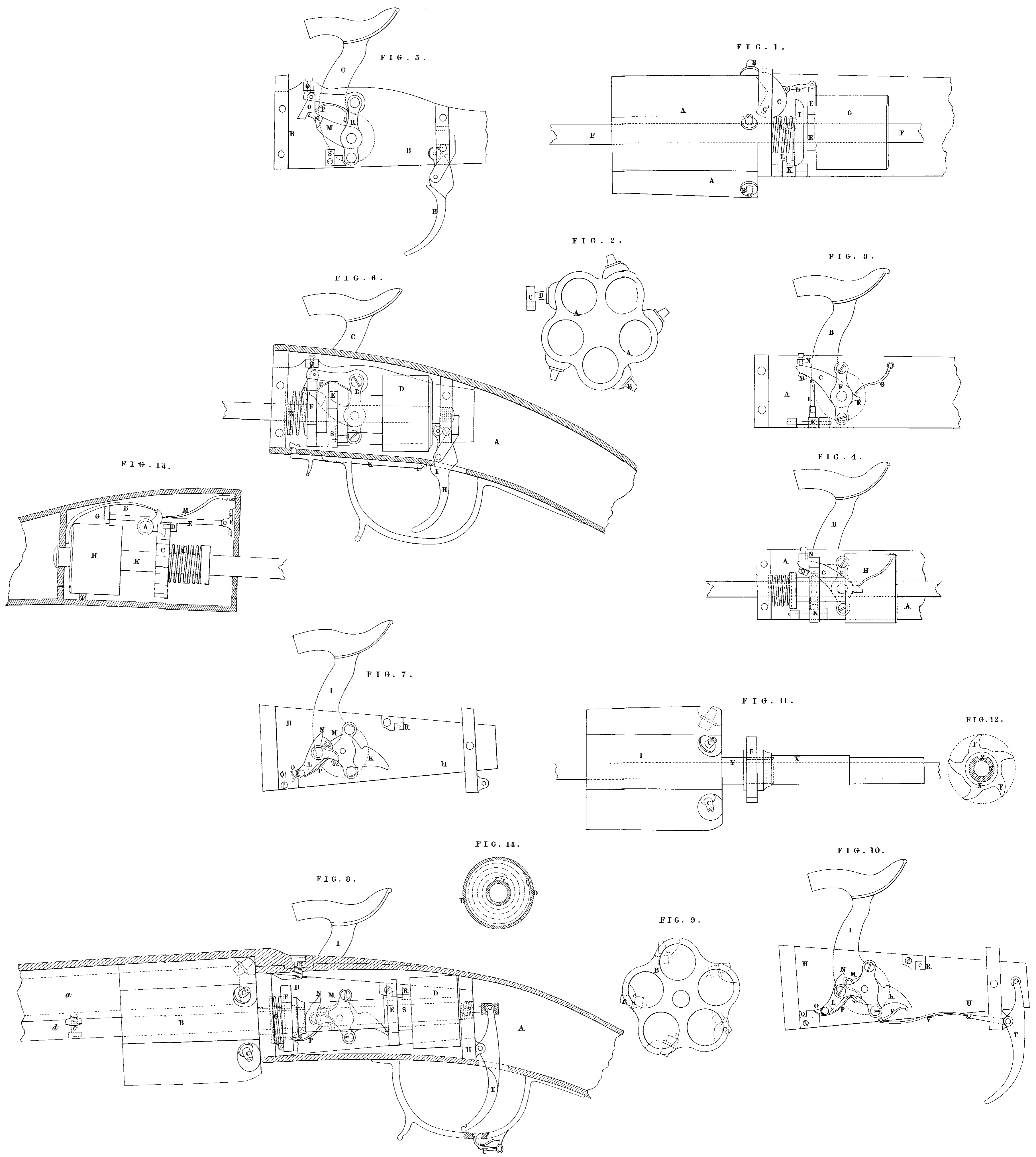
Figure 1, is a side view of part of a gun, shewing some of-the parts; and Figure 2, is an end. view of the revolving breech, shewing the position of the nipples in relation to the barrel and the stop against which they strike. In these Figures the. same letters indicate the same parts. A, is the revolving breech; B; the nipple; C, the.move able stop which receives the blow of the nipple; it moves upon an axis C¹; D, is a link connecting the collar E, with the stop C; E, is the, collar attached to the barrel G; but which does not prevent its turning; G, G, is the barrel or case containing a spiral spring; H; is a spring which brings back. the mechanism to the position shewn in the Drawing when by the action of the trigger it has been pushed forward; I, is a wheel having an equal number of teeth to the number of the small barrels: of the revolving breech; this wheel prevents the barrel. G, from turning, being always connected with it; K, is a stop piece which prevents the whole mechanism from turning; L,is a small spring which keeps the stop K,in a proper position for preventing the wheel l, from turning in that way which would unrol the spiral spring contained in the barrel Gr, but which permits the wheel to turn in the contrary way, in order that the stop K should act to prevent the spiral spring from being drawn back.
The manner in which the whole system acts is as follows:— When the trigger is pulled the barrel G is pushed-forwards, and consequently the collar I, which, by means of the connecting piece D, turns the stop C, and places it over the nipple, where it receives, the shock when the Darrel turns round, which takes place when the wheel I, has advanced sufficiently far to escape the stop K, and the fire-arm will then be discharged; and by letting go the trigger the whole of the. mechanism will be brought back to its position by the spring H, which during the previous action was compressed, and the gun will be ready to be again discharged. It-will be evident that the spring will not unrol more than one fifth or, one sixth of a turn for each time.the gun is fired, according. to the number that it is made for, either five or six.
I will now describe an arrangement where a cock is used for striking against the nipple. Figures 3, and 4, shew views of a part of a fire-arm. A, is the plate to which: the lock is fixed; B; is the cock; C, is a lever connected to the cock, which lever bas joined to it a cleat D, which-acts on a wheel and a tail piece I; upon which acts the spring G; E, is the bearing of the lever; G, is a spring which raises the cock after the gun has been discharged; H, is the barrel or case containing the spiral spring; I, is a wheel fixed to the barrelH, which prevents its turning; K; is a stop which prevents the wheel I, from turning; consequently the whole of the mechanism; L, is a small spring for the same purpose as that described in Figure 1; M, is the spring for bringing back the mechanism to its primitive position after the gun is fired; N, is a stop which limits the course of the lever C, and consequently the rise of the cock.
In pressing upon the trigger the barrel will advance and carry with it the wheel I, which, as soon as it has passed the stop K, will be free. It turns in drawing the cleat D of the lever C, in front of which it is placed, and consequently lets the cock fall upon the nipple, which is so placed to receive the blow, and so discharges the gun. The same movement of the spiral spring turns the and causes the cock to descend upon the nipple; the spring will thence force back the wheel I which takes into the stop I; at the same time it releases the cleat D of the lever C, which will then be free on the spring G, will bring it back into the position shown in the Drawings, ready to be again discharged. In this arrangement the spiral spring only unrols one fourth, or one fifth, or one sixth, according to the number of times the fire-arm is to be discharged. To draw up the spiral spring of the barrel it is only necessary to take the revolving breech, either with the hand or with a key, and to turn it in the proper way, the stop K, not, interfering with the movement of the wheel I.
Figures 5, 6, and 7, shew another arrangement, in which the same letters indicate the same parts in these Figures. In this arrangement the spiral spring causes the cock to descend, then turns the revolving breech, and then to raise the cock. A, shews the sides of the case which encloses the lock; and B, is the plate; C, the cock; D, the barrel which contains the spiral spring; E, is a wheel, at all times fixed to the barrel, and which actuates the cock and cause it to descend; I, is a wheel to raise it again after the gun is discharged, and also to turn the revolving breech to which it communicates its motion; this wheel can turn independently of the barrel D; the spiral spring communicates its motion by means of a catch, shewn in Drawing; Figure 14, upon which it is fixed at one of its ends; G, is the spring which brings back the machinery into the position shewn before the discharge takes place; H, is the trigger, one end of which has a small friction wheel which presses against the barrels containing the spiral spring; there is a small notch I, in the trigger, into which the end of the sliding piece I passes, in order to fix the. trigger and prevent it being pulled whilst the spring of the barrel: D, is being drawn or wound up; L, is a spring for the purpose of drawing back this sliding piece when it is required to pull the trigger; M, is a lever affixed to the axis of the cock, to which is attached a tongue piece N, against which successively strikes’ the wheels E, and F, in order: to lower and raise the cock; O, is a stop piece which: prevents the cock from being raised too high, and prevents the wheels N, from turning in the way which would raise the cock, but does not. prevent its turning the other way the distance required; and when in. this position the trigger may be securely fixed by passing the sliding piece K, into the notch of it; P, is a spring to bring back the stop O, into the position shewn in the Drawing; Q, is a screw: to regulate the position of the piece O; R, is a bridle or cross piece; S, is another stop to prevent the wheel E, from turning when the mechanism is in. the position shewn in the Drawing. In pressing upon the trigger. motion will be given to the spring barrel, and thence to the wheels E, and 17; the wheel I, will let go the-stop N, and rest upon the stop O; at the same time the wheel E, will quit the stop S, and lay hold of the stop N, and thus acts upon the cock by letting go of the trigger; the spring G will force back the mechanism, and the wheel E will let. go from the stop N, and descend to-the stop S. To draw up again the spiral spring the wheels E and F, are pushed forward by means of the trigger, so far that the wheel F, would let go-of the stop N before the wheel E had let go the stop S; the mechanism should then be retained in this position. by sliding the piece K, into the notch in the trigger; then the arrangement of the stop O, allows the wheel to be turned in the way, which draws up the spring as, in the preceding Figures, by turning the revolving breech, either by hand or by a key.
Figures 7, 8, 9, 10, show another arrangement, where, as in the before described. Figures, the cock and the small barrels of the revolving breech are successively released and the cock again raised. The same letters are used for similar parts. A, is the case which-encloses the whole of the mechanism; B, is the revolving breech; which may contain as many bores or barrels as may be required; C, are the nipples on which the caps are placed; D, is the case or barrel containing the spiral spring; E, is the wheel which acts against the cock to let it down; and T, the. wheel which raises it again; G, is a spring for the same object as the one previously described; H, is the plate of, the lock; I, is the cock; K, is a lever to the cock; L, the counter lever, which is connected to it by means of a pin, and receives its movement from it, and which pin slides in the groove N, which carries the counter lever L, at the end; O, is a hinge; in order that the wheel F, may not be prevented from turning when it is desired to draw up the spiral spring; P, is a small spring to keep the piece O, in a suitable position; Q, is a stop which prevents the wheel F, from turning after it has quitted the stop of the counter lever; R, is a stop which prevents the wheel E, from turning after it has quitted the lever K; T, T is the trigger, which communicates motion to the case or barrel containing the spiral spring; U, is a hook which acts upon the trigger for. the same object as the sliding piece K; described in the Figures 5, and 6; V, is a spring, one end of which is connected to the trigger and the other to the lever K; of the cock, which greatly assists in discharging the gun when pulling the trigger; the mode of action is similar to that described in the previous Figures, and the spring is drawn up in. the same manger as before explained a, is the barrel; 3, is a band of iron placed over the whole length of the barrel, and which serves to connect the barrel to the box; c, is a screw which fixes the end of the hand of iron to the box; d, is a shaft at the under side of the main barrel, which serves as the axis of the spiral case, the wheels E and F, and the revolving breech; e, is a screw which connects this shaft d, to the main barrel.
Figures 11; and 12; show how the collar X. (upon which is fixed the wheel F) communicates motion to the revolving breech. On this revolving breech is a small collar Y, in the side of which is a groove, into which works a tenon Z, within the collar X; by this arrangement the collar N, and consequently the wheel F, cannot turn without also turning the revolving breech.
The arrangement in Figure 13, shows that the, spiral spring only raises the cock and.turns the breech, and a large spring placed over the spiral spring releases the.cock and discharges the gun: A, is the lever in connection with the cock, having two claws; against one the large spring B acts, and releases the cock; and against the other claw the wheel C acts, to raise up the cock and draw back the large spring; D, is a stop against which the wheel C, rests when it has quitted the lever A. In order that this stop should not prevent the, spiral spring from. drawing back it is fixed upon a small red with a hinge, as shewn at, the end F, having a guide piece G; H, is the case containing the. spiral spring; I, is a stop to prevent this case from turning; K, is a shaft or axis to which is fixed one of the ends of the spiral spring, and which transmits the movement to the wheel C; I, is a spring, for the same object as described in the previous Figures. M,is a small spring which keeps the rod TS, and the stop D, in a proper position. The action of this arrangement is the same as that previously described, I would remark that the arrangement which I have found best to answer in operation is that described in Figures 7, and 8.
Having thus described the nature of the Invention, and the manner of performing the same, T would have it understood that I lay no claim to the application of revolving breeches to fire-arms, they having been before used; nor do I confine myself to the precise details herein given, so long as the character of the Invention be retained. I would have it understood that what I claim as the Invention communicated to me, is,—
First, the mode of constructing fire-arms with revolving breeches in such manner that the act of pulling the trigger will discharge the gun, and by withdrawing the pressure therefrom the breech will revolve and bring up a fresh barrel to be discharged, the other parts returning to their original position, as herein described at Figures 4, 5 6,7, 8,9, 10, 11, 12, and 13.
And, secondly, in the mode of constructing fire-arms with revolving breeches applied thereto in such manner as to dispense with the cock or hammer, by bringing each nipple, having a cap thereon, successively in contact with a moveable stop, which will explode the cap and so discharge the gun, as herein described at Figures 1, 2, and 8.
In witness whereof, I, the said Moses Poole, have hereunto set my hand and seal, this Fourteenth day of April, in the year of our Lord One thousand eight hundred and forty-two.
MOSES (L.S.) POOLE.
ND BE IT REMEMBERED, that on the Fourteenth day of April, in the year of our Lord 1842, the aforesaid Moses Poole came before our said Lady the Queen, in Her Chancery, and acknowledged the Specification aforesaid, and all and every thing therein contained and specified, in form above written. And also the specification aforesaid was stamped according to the tenor of the Statute made for that purpose.
Inrolled the Fourteenth day of April, in the year of our Lord One thousand eight hundred and forty-two.