
US 189360
UNITED STATES PATENT OFFICE.
OWEN JONES, OF PHILADELPHIA, PENNSYLVANIA.
IMPROVEMENT IN REVOLVING FIRE-ARMS.
Specification forming part of Letters Patent No. 189,360, dated April 10, 1877; application filed, August 22, 1876.
To all whom it may concern:
Be it known that I, OWEN JONES, of Philadelphia, in the county of Philadelphia and State of Pennsylvania, have invented a new and useful Improvement in Cartridge-Extractors; and I do hereby declare that the following is a full and exact description of the same, reference being had to the accompanying drawings, and to the letters of reference marked thereon.
This invention consists, mainly, first, in the combination, with a relatively-fixed extractor-plate, a sliding cylinder, and tilting barrel, of an intermediate-rack mechanism for uniting the barrel to the cylinder and communicating the movement of the former to the latter without lost motion; and, second, in certain details of construction, which, in connection with the foregoing, will be fully described hereinafter.
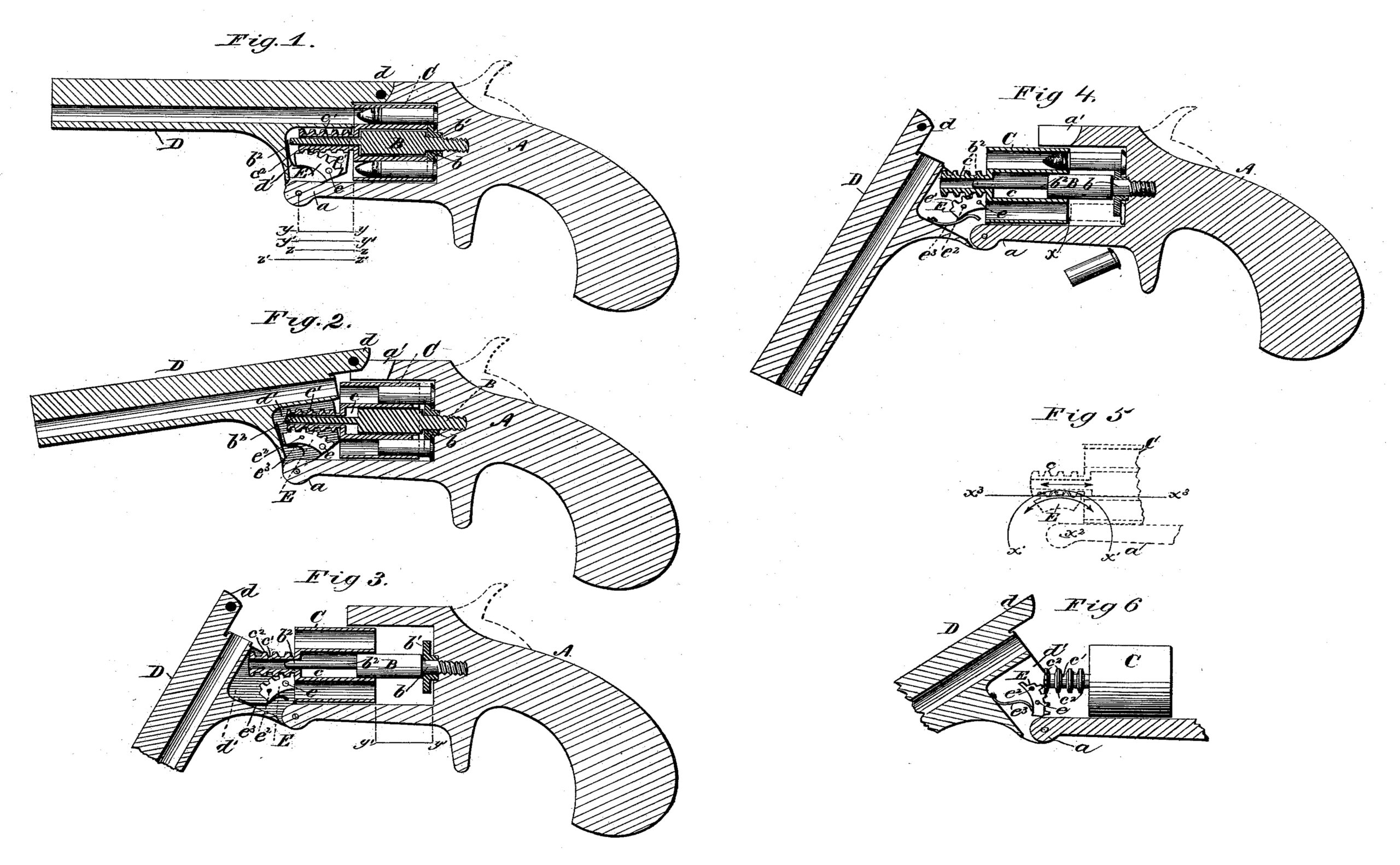
In the drawings, Figure 1 represents a sectional elevation of a pistol having my improvement applied thereto, the same being represented as loaded, ready for firing; Fig. 2, a similar view, representing the spent cartridges partially extracted; Fig.3, a similar view, with the cartridges entirely discharged ; Fig. 4, a similar view, representing the retention of a loaded cartridge and the discharge of a spent shell; Fig. 5, a view representing the position of the rack devices relatively to the hinged point of the barrel; and Fig. 6, a view representing the position of the segmental rack-bar when thrown forward by its spring e3 to engage with the sleeve of the cylinder.
To enable others skilled in the art to make and use my invention I will now proceed to describe fully its construction and manner of operation.
A represents the frame of the pistol, constructed, generally, in any suitable manner, and of any proper size, but provided, essentially, below with a projection, a, to which the barrel is hinged, as shown, and above with a locking-socket, a1, of any proper construction.
B represents the center-pin, rigidly secured at its rear end to the frame A, which is provided at its rear end with a recess, b, adapted to receive and hold the extractor-plate b1 free to revolve thereon, as shown. b2 represents the front end of the pin, the diameter of which is less than its rear portion, for purposes hereinafter explained.
C represents the cylinder, constructed. generally in the usual, well known, or other proper manner, but provided, essentially, with a central recess, c, adapted to receive the main portion of the center-pin, and a projecting sleeve, c1, adapted to receive the front end of the pin, the latter being provided upon its exterior surface with a series of collars or annular teeth or flanges, c2 c2, as shown.
D represents the barrel, of proper construction, hinged in any suitable manner to the frame A, and having the locking portion d and recess d1, as shown.
E represents a segmental rack bar or block, pivoted within the recess d1 by means of the pin e, as shown. This is provided with teeth el, adapted to engage with the annular teeth up on the sleeve, as shown. e2 represents a pin, by means of which the rack-bar E is secured in its proper position. e3 represents a spring, by means of which the rack-bar, when its pin e2 is removed and the parts are disconnected, is thrown backward, as shown in Fig. 6, into proper position to engage with the sleeve, when the disconnected parts are again brought together.
The operation of my extractor will be readily understood.
The pistol having been fired, the cartridge-shells may be discharged by simply unlocking the catch and tilting the barrel. By means of the movement of the barrel the rack-bar is caused to actuate the cylinder and draw it away from the relatively-fixed extractor-plate, and hence the shells held thereby, being left unsupported, fall out.
It will be observed, as indicated at x in Fig. 4, that the cylinder has a longitudinal movement slightly in excess of the length of the cartridge-shells, and hence these are discharged with absolute certainty when the barrel is tilted. This movement of the cylinder, however, on the other hand, does not equal the length of a loaded shell, as shown in the same figure, and hence it follows that, while the spent shells may be extracted at any time with absolute certainty, the loaded shells cannot, by any possibility, be extracted or drawn out.
It will be observed, also, as indicated in Fig. 5, that the rack-bar is a segment of a circle, x’, struck from the hinge-point x2 as a center, and that the lower line x3 of the sleeve of the barrel cuts this circle at its highest point, in consequence of which it follows that, when the barrel is tilted on its hinge, the teeth of the rack-bar, rigidly attached thereto by means of its pins, move in the arc of a circle coinciding at the point of contact with the horizontal line of the sleeve’s movement, and hence they successively act upon the corresponding teeth of the sleeve, and give the latter movement in a uniform straight line without strain or without lost motion.
It will be observed, also, that by means of the annular teeth or flanges of the sleeve the cylinder is permitted freely to revolve.
It will be observed, also, that the hinge-point of the barrel is located in advance of the front end of the cylinder a distance, y y, Fig. 1, equal to the desired movement of the latter, y’ y’, Fig. 3, so that proper space is afforded for the movement without danger of contact between the parts. This distance, as before observed, slightly exceeds the length of the spent cartridge z z, Fig. 1, but does not equal the length of a loaded cartridge, z’ z’, Fig. 1.
Some of the advantages of the described construction are as follows:
The cylinder is actuated to extract the cartridges without lost motion by the barrel serving as a lever, so that tightly-jammed cartridges are easily and quickly extracted.
The parts employed are few in number and simple in construction, so that the expense of manufacture is small, and there is no special liability to get out of order.
Having thus fully described my invention, what I claim as new, and desire to secure by Letters Patent, is—
1. In combination with a fixed extractor-plate, a sliding cylinder, and a tilting barrel, the intermediate rack mechanism for uniting the barrel to the cylinder, substantially as described.
2. In combination with a sliding cylinder and a lever-barrel for moving the cylinder, intermediate rack mechanism for communicating the movement of the former to the latter without lost motion, substantially as described.
3. The combination of the rack-bar with the teeth of the cylinder, the former being adapt- ed to move on an arc of a circle struck from the pivot-point of the barrel, and the latter on a horizontal line cutting the highest point of the circle, as and for the purpose described.
4. In combination with a lever barrel provided with a pivoted rack-bar, a sliding cylinder, having annular teeth, as described.
5. The combination of the following elements: a tilting-lever, a sliding cylinder, and a pivoted rack-bar, having a removable securing-pin adapted to engage with the cylinder, as described.
6. The combination of the following elements: a fixed center-pin, a fixed extractor-plate, a sliding cylinder, a tilting barrel, and rack mechanism for uniting the barrel to the cylinder, substantially as described.
7. In combination with the pivoted rackbar E, the spring e3, as described.
8. In combination with a tilting barrel for sliding the cylinder a limited distance, the cylinder having the hollow sleeve, and the center-pin having the extension b2, the construction being such that the cylinder is guided and supported in all its movements by the pin, substantially as described.
OWEN JONES.
Witnesses:
HARRY C. CLARK,
M. E. STALLINGS.