
US 213221
United States Patent Office
Paul Mauser, of Oberndorf, Würtemberg, Germany
IMPROVEMENT IN REVOLVING FIRE-ARMS
Specification forming part of Letters Patent No. 213221, dated March 11, 1879: application filed July 26, 1878
To all whom it may concern:
Be it known that I, Paul Mauser, of Oberndorf, Würtemberg, in the Empire of Germany, have invented certain new and useful Improvements in Repeating Fire-Arms or Revolvers, of which the following is a description, reference being had to the accompanying drawings, forming part of this specification.
This invention relates to a revolver or a repeating-pistol of novel construction, differing materially from the systems hitherto adopted. The rotation of the chambers in this revolver is effected by the act of cocking or drawing back the hammer, as in recent American revolvers. The hammer is cocked by the thumb before each shot. This has the effect of reducing the speed of firing to a certain extent, which, however, is compensated for by the much greater security of the charge. This repeating fire-arm or revolver is characterized by the great simplicity of its mechanism. It may be constructed entirely with thirty-three pieces only, while many-other revolvers sometimes contain fifty-six. It consequently admits of being taken to pieces with great facility.
For the purpose of cleaning the revolver, a screw only requires to be unscrewed. The whole of the parts may be then taken out by hand and cleaned and oiled.
A further peculiarity consists in the novel construction of the extractor.
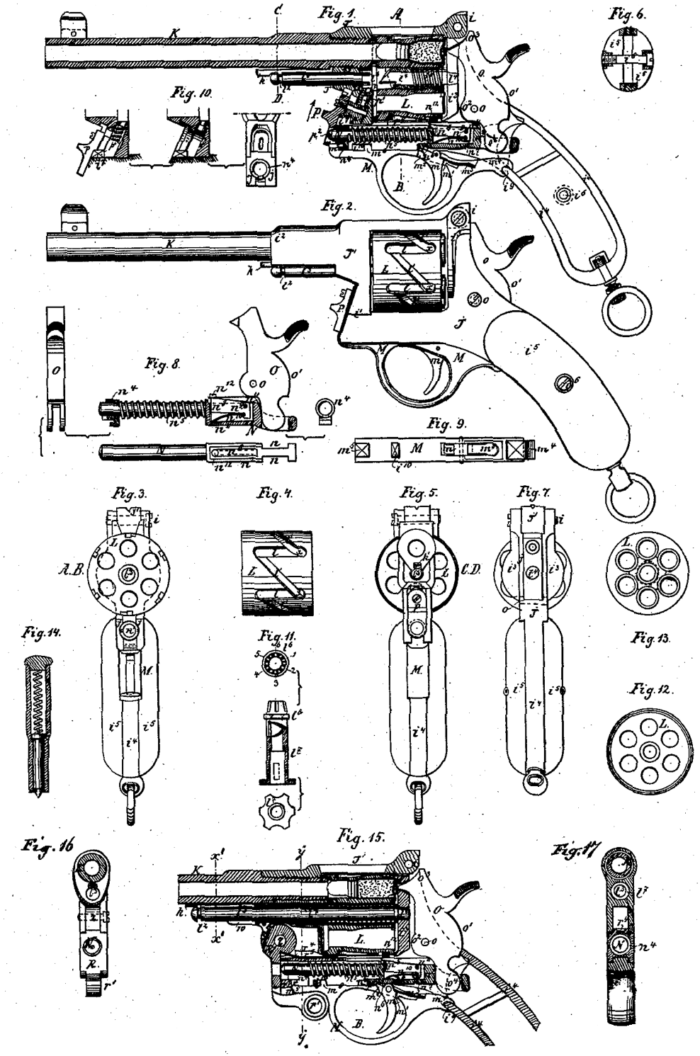
Referring to the accompanying drawings, Figure 1 is a longitudinal section through the center of the revolver, showing the whole of internal mechanism. Fig. 2 is an external elevation of the same. Fig. 3 is a transverse section taken along the line A B, Fig. 1. Fig. 4 is an external side elevation of the cylinder,
showing more particularly the grooves cut in it’s circumference, in which the pawl or piece works which causes the rotation of the said cylinder. Fig. 5 is a transverse section taken along the line C D Fig. 1, viewed from the front. Fig. 6 is a transverse section of the stock, showing the attachment of the wood. Fig. 7 is a view of the revolver seen from behind. Fig. 8 is a detail, showing the hammer and the spring and sliding bolt by which it is actuated. Fig. 9 is a plan of the trigger-guard plate. Fig. 10 represents details of the safety-slide. Fig. 11 shows three detail views of the extractor. Fig. 12 is a view of the fore end of the revolving cylinder. Fig. 13. is a view of the rear end of the same. Fig. 14 is a sectional view of a key for pressing back the socket-guide of the sliding bolt which controls the hammer when requiring to detach the latter and accompanying parts. Fig. 15 is a further sectional view, in part, of the fire-arm; and Figs. 16 and 17 are transverse sections on the lines x’ x’ and y” y” respectively.
The principal parts are marked in the drawings with capital letters, and the smaller parts of which the principal parts are composed are marked with the corresponding small letters, with the addition, where required, of numbers.
J J’. is the body, frame, or case of the revolver. It consists of two parts, J J’, which are connected together by a hinge, i, and open at i1.
K is the barrel; L, the revolving cylinder; the trigger-guard plate; N, the sliding bolt acting on the hammer; O, the hammer; P, the safety-slide.
The body or case J J’ is of iron or steel, with flat sides, and hollowed out internally to provide room for the lock. The front part, i2, is somewhat thickened, and provided with an internal screw for the reception of the barrel. Behind the revolving cylinder the body is spread out in the form of a circular recoil-plate, i3. The rear part is completely hollowed out, and consists of a thin band, i4, Figs. 1 and 6, which is embedded in the wooden stock i5. A single screw, i6, is sufficient to secure the wooden stock to the metal band i4 .The body or case J’ is cut away at the upper part, over the revolving’ cylinder, in such a manner as to admit as little dirt as possible. Any gas which may be present is thus enabled to escape readily.
The back sight is formed upon the hinge.
A recess is formed in the back of the body for the reception of the hammer, which fits closely therein, and is provided with two curves, o1 o2, which fit as closely as possible against the sides of the recess, and, being struck from a common center, o, serve to prevent the entrance of dirt at this part. The hollow of the body is closed underneath by the trigger-guard plate M. Underneath the revolving cylinder a narrow opening or slit only is formed in the body or case for the passage of the pin for effecting the rotary motion of the cylinder, in which the said pin travels to and fro. The cylinder itself serves to close this opening and prevent any dirt from entering at this point.
At the front part, where the end of the sliding bolt for actuating the hammer is passed through the body or case, the opening is closed by the bolt itself and a collar or socket, n4, which surrounds it.
The trigger m entirely fills the hole in the trigger-guard plate, through which it communicates with the inner part of the lock. Its detent m2, with the part of the sliding bolt N in which the half-cock and full-cock notches n6 and n7 are formed, closes the front part of the hole. The hinder part, m1, of the same is closed by the trigger-spring m3.
In order to admit of the extraction of the exploded cartridge-shells, the body or case is so constructed and arranged as to be readily opened by pushing up the safety-slide P in the direction of the arrow, whereby the nose i7 is liberated from the catch p. The position of the hinge with relation to this catch is such, as shown in Fig. l, that this mode of fastening is perfectly secure.
There is nothing new to be described in the barrel K, which is constructed in the usual manner, and screwed into J’.
The revolving cylinder L, on the other hand, differs considerably from the revolving cylinder usually employed. It contains six chambers, as usual, and turns upon a center-pin or axis, l3, one end of which is supported in a bearing, i8, formed in the body J’, and the other end, which is of conical shape, fits exactly into a hole bored for the purpose in the center of the recoil-plate i3.- The hinder part of the center-pin is of conical shape, to facilitate its passing in and out of its bearing in the recoil-plate on opening or closing the case.
The front end of the center-pin is provided with a small annular groove, l2, which engages with a projection formed on a spring k, this spring being located, as shown in the section, Fig. 5, in a groove formed under the barrel, and having its rear end bent up at right angles and held between a shoulder on the barrel and the case J’.
A steel bush, consisting of two parts, l6 l7, termed the “extractor” is passed over the center-pin l3. The said bush is shown separately in Fig. 11.
The conical end l6 fits into a conical hole bored in the case. The space between the case and the cylinder is occupied by a small filling-piece or washer, 7. Six notches, l 2 3 4 5 6, are formed in the conical part, for a purpose hereinafter explained.
The two parts l6 l2 of the extractor are coupled or connected by a sectionally spiral or rag-clutch construction of their meeting ends, which, when the part l6 is held stationary, prevent the rotation in a given or backward direction of the part l7, in common with the revolving cylinder L, with which said part l7 is connected, as hereinafter described, but which spiral or rag-clutch connections,when said cylinder is rotated in a reverse direction, allow the part l7 to rotate in common with the cylinder by it’s rag-clutch riding over the rag-clutch end or portion of the part l6, when the latter is locked or held from rotating in common with the cylinder.
The part l7 is provided with a flange, which is completely buried in a corresponding
recess formed in the end of the revolving cylinder, so that its outer surface is flush with the rear end of the said cylinder. The flange is sufficiently broad to extend as far as the cartridge-chambers, and is there cut away in six places corresponding ,with the six chambers, so as to fit under the flanges of the cartridges.
In order to remove the cartridge-shells from the chambers by means of this extractor, the case is opened by pushing up the safety-slide P in the direction of the arrow, whereby the nose i7 is liberated from the catch p. At the same time, however, the flattened end of the pin p1 engages with one of the notches 1, 2, &c. The fore part, l7, of the extractor is provided with a projection, which works in a groove formed in the revolving cylinder. When the pin p1 is caused to enter one of the notches by pressure on the sliding piece P, the cylinder L is only capable of rotating in one direction, viz., in that direction in which the cam on the part l7 is able to ride over the cam on the part l6. The perpendicular ends of the cams prevent their rotation in the opposite direction. As the cylinder rotates the part l7 is pushed out by the action of the cams, and expels the shells of the cartridges, so that they all drop from the chambers simultaneously into the hand.
The circumference of the revolving cylinder L is provided with grooves l l2, which pass round it in a zigzag direction. The grooves l are parallel with the generating line of the cylinder. The inclined grooves l1 of each connect one end of one of the parallel grooves l with the opposite end of the next corresponding parallel groove. The bottoms of the longitudinal grooves are inclined and rise from the front end toward the connection with the inclined groove, Fig. 4. The pawl or pin for actuating the revolving cylinder works in this groove, and is pushed down it by the act of cocking the hammer.
The pawl consists of a small tongue, n3, which is centered on a pin, l9, and moves in a recess formed in the sliding bolt which actuates the hammer. A spring, n10, forces the tongue or pawl upward in the recess. Its end n11 bears against the sliding bolt. When the hammer O is cocked its bifurcated end o4 pushes the sliding bolt N forward.
The projection n12 on the pawl n8, which is forced forward with the bolt, engages in one of the .inclined grooves l1, and, as it moves forward in a line parallel with the axis of the cylinder, it causes the latter to describe a fraction of a revolution. On reaching the end of the inclined groove l1 the projection n12 enters the deep end of one of the parallel grooves l, and at the same time the detent m2 of the trigger m engages in the full-cock notch n7 under the sliding bolt N. On pulling the trigger the detent m2 releases the bolt N, which slips back,”‘carrying with it the pawl n8, and the projection n12 slides back along one of the parallel grooves l without moving the cylinder. During this motion the projection n12 passes from the deep end of the parallel groove l along the inclined bottom of the groove to the shallow end, where it suddenly drops into the deep end of the next inclined groove at the angle
x x, Figs. 2 and 4. On cooking the hammer again the same operations are repeated, so that the revolving cylinder is again turned round one-sixth of a revolution and another chamber brought into position for firing. On cocking the hammer the spring n5 is compressed. The said spring bears against the socket or guide n4, Figs. 1 and 8, at one end, and against a shoulder, n2, formed on the bolt N at the other end.
The hammer fits into the recess n n formed in the sides of the bolt N, Fig. 8.
The sliding bolt N moves in a straight line in the direction of it length, being guided at the front end by the socket n4, and behind by l the cylindrical guide n1, Fig. 3.
The half-cock notch n6 is of such a shape that the detent of the trigger is firmly retained in it when the bolt is drawn back. The full-cock notch n7 is cut at a more obtuse angle, so that a comparatively slight pressure of the finger on the trigger suffices to release the bolt, which is impelled backward by the action of the spring. The same movement throws the hammer forward, bringing its nose suddenly into contact with the cap, and explodes the cartridge.
The trigger-guard plate M is connected to the end part of the case in the following manner: A hook, m4, embraces the angle i9, and a hook, m5, at the forward end engages in a hook, n4, formed on the socket or guide of the sliding bolt, and which is retained in position by the spring n5. A projection, m6, on the plate bears against a bridge or projection, i10, on the case. This simple method of fastening the trigger-guard plate thus enables all screws to be dispensed with, and admits of its being unfastened by means of an instrument in the form of a hollow key, Fig. 14, which is pressed in until the hook m5 is liberated. The trigger-guard plate will then drop out, and the socket or guide will be pushed out by the spring. The screw o of the hammer may then be unscrewed and the hammer taken out. The sliding bolt N may be then removed by pressing the projection n12 on the pawl into the recess i11, and drawing the bolt back until its front end can be passed behind and under the bridge i10, and thus enable it to be withdrawn with facility.
The trigger m is maintained in the notches by means of a trigger-spring, m3, which is fitted into a dovetailed recess in the trigger-guard plate
The safety-slide P serves three purposes: In the first place it serves to connect together the two parts of the case J J’ at their point of contact i1, as the spring which is wound round the pin p1 presses the catch p under the projection i7; secondly, it serves as a protection (whence its name) against the accidental discharge of a shot in case the two parts of the case or body are prevented from coming together at i1 by reason of a grain of sand, for example, or other small foreign body, becoming interposed between the two parts. Thus, when the two parts are not properly closed the sliding bolt actuating the hammer cannot pass through the opening p2, but comes into contact with the sliding piece P. In this way the discharge is prevented. When the opening between the parts i1 is small and the resistance insignificant, the rounded end of the sliding bolt penetrates into the hole p2, and brings the parts together, whereby it is enabled to pass freely through the opening.
In order to take the revolver to pieces for the purpose of oiling the parts, it is necessary to proceed in the following manner: The barrel being held in the left hand, the safety-slide P is pressed back in the direction of the arrow, and the case opened by turning the parts on the hinge-pin i. The spring k is then depressed, and the spring l8 compressed at the same time by turning they revolving cylinder, and the center-pin of the same will then be pushed out by the action of the spring. The revolving cylinder is then taken out and the two parts l6 and l7 of the cartridge-extractor removed. The pin o, which forms the axis of the hammer, is then taken out with a screwdriver, whereupon the hammer itself may be removed.
The socket-guide of the bolt for actuating the hammer is now to be pressed back by means of an instrument forming a species of hollow key, Fig. 14, by placing the spring-point of the instrument in the center of the sliding bolt. This releases the trigger-guard plate, which drops out, as well as the socket, which is forced out by the spring n5. The spring n5 itself may then be taken out. The projecting piece n12 on the pawl is then depressed into the recess i11, and allows the sliding bolt N to be drawn back and taken out of the under part of the case. All the parts can now be cleaned and oiled conveniently, and then put together again in the same order.
I claim-
1. The sectionally-constructed extractor l6 l7, of a cam form or construction at the meeting ends of the sections, in combination with the safety-slide P, having a pin or projection, p1, arranged to enter any one of a series of notches in the section l6 of the extractor, the rotating cylinder L, with which the section l7 of the extractor, made capable of a longitudinally-sliding motion, is fitted to turn, and the cartridge-shell-extracting flange at the other end of said section l7, essentially as described.
2. The combination of the safety-slide P, provided with a spring-catch for holding and locking the two parts J J’ of the case together, with the sliding bolt N, actuated by the hammer, and arranged to enter a cavity or aperture in said slide when the two parts of the case are closed, whereby not only the two parts of the case are held together, but the cocking of the hammer when said parts are not closed is prevented, and the rotating part of the extractor is prevented from turning, substantially as specified.
3. The sliding bolt N, in combination with the pawl n8, the spiral spring n5, the collar or socket n4, the hook m5, and the hammer O, substantially as shown and described.
4. The sliding bolt N, having recesses n n in its sides, in combination with the hammer O, constructed to enter within said recesses, essentially as described.
5. The trigger-guard plate M, provided with hooks m4 m5 at its opposite ends, and an intermediate projection, m6, in combination with the projection i10 on the case, the socket n4, and and the angle piece i9, substantially as specified.
PAUL MAUSER.
Witnesses:
Louis Basse,
Ludwig Maschmann