
USA 14710
UNITED STATES PATENT OFFICE.
GUSTAV A. BLITTKOWSKI AND FREDERICK WM. HOFFMAN, OF NEW YORK, N.Y.
IMPROVEMENT IN REVOLVING FIRE-ARMS.
Specification forming part of Letters Patent No. 14,710, dated April 22, 1856.
To all whom it may concern:
Be it known that we, Gustav Adolph Blittkowski and Frederick William Hoffman, late of Germany, but now of New York, county of New York, and State of New York, have invented certain new and useful Improvements in Revolving-Chamber Fire-Arms; and I do hereby declare that the following is a full, clear, and exact description of the same, reference being made to the annexed drawing, making a part of this specification, in which—
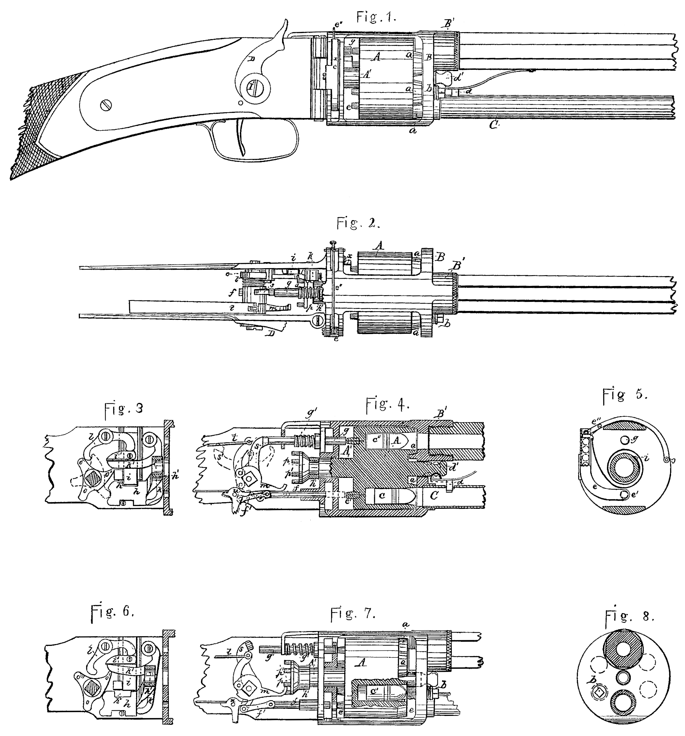
Figure I is a side view or elevation. Fig. II is a top view or plan. Figs. III, IV, V, VI, VII, and VIII are parts in detail.
Similar letters indicate similar parts throughout.
Our improvement in repeating fire-arms consists, mainly, in the following particulars, viz: in the method of working the revolving cylinder or breech-chamber, whereby the cartridge is deposited, rammed, the caps applied, and the charge conveyed to the gun-barrel by the act of cocking, and in the peculiar arrangement of the lock, whereby the several reciprocating and rotating motions of the breech-chamber, together with the operation of priming and firing, are produced. The breech-chamber has two movements— one rotating upon an axis, and the other vibratory in the direction of said axis. The cavities in the breech-chamber are bored out as usual, the nipples, however, being placed on the back and in a line with the bore. On the front of the breech-chamber there is likewise around each cavity a beveled projection, which will fit within a beveled cavity of like character at the base of the barrel. In order, therefore, to be able to turn the breech, it must first be drawn back sufficiently to allow this projection to clear. The return movement is made use of to ram home the ammunition, which has in the meantime been deposited from the magazine. Thus this vibratory motion of the breech enables us effect the locking of the same to prevent rotation, it forms a very close and secure joint where it joins the barrel, and it effects the feeding and ramming of the load.
At A is the breech-chamber, supported upon a shaft lying parallel to the barrel, and between two strong circular plates framed together. The shaft extends quite through both of these plates, being prolonged in the back part, so as to enter the lock, where the vibratory and rotatory motions are given, to effect the several changes for loading and firing.
On the outside of the plate B there are two nozzles, one placed directly over the other. The larger of these is at the top, as shown at B’, and is where the barrel is screwed on. The lower nozzle is for securing the magazine-tube C.
In the breech there are six charge-chambers. Thus, when a chamber is opposite to the barrel, there will also always be one opposite to the magazine-tube, as in the sectional view, Fig. IV. The charges drop into these chambers from the magazine by gravity, the nozzle of the gun being elevated after each fire sufficiently high for the purpose. As the cartridge fits the chamber snugly by reason of a slight taper, it will require force to send it quite home. This is accomplished as follows: In bringing the hammer of the lock to half-cock, the breech A is drawn back, so that the beveled mouths a, be fore mentioned, will stand clear of the plate B, and also clear of the beveled concavity in the inside of the nozzle B’. The breech is then free to revolve. Carrying the hammer on to full-cock effects the two following motions: First, it rotates the breech one chamber onward, and when that motion is completed the second one— viz., in the direction of the axis— takes place, which returns the breech back to its general place against the plate B, whereby a enters the concave in the nozzle. Through the plate B there is a blunt pin, b, screwed, so as to render it capable of adjustment. This is placed one step forward, and in such position as to point directly into one of the chambers whenever there is one opposite to the barrel and mouth of the magazine. Thus, by pulling the hammer of the lock to half-cock, the breech will be drawn back from the position shown in Fig. IV to that shown in Fig. VII. Continuing to draw back the hammer, the breech will begin to rotate and transfer the cartridge c, Fig. IV, to the position c’, Fig. VII, when it will stand opposite to the point of the pin b. The hammer still moving back, so soon as the rotary motion ceases, it thrusts forward the breech toward the plate B, when the pin b enters the cavity and drives home the cartridge to the position shown at c”, Fig. IV. Thus there are always four charges in the breech— viz., one just sent in from the magazine, as at c, Fig. IV; one in the act of being rammed by the pin b, one in the chamber opposite the barrel, as at c”, Fig. IV, and one in a chamber be tween the pin b and c”.
As the charges fall from the magazine by gravity into the chambers in the breech some means must be used to prevent them moving on when the breech is withdrawn preparatory to rotating it. At d, Figs. I and IV, is a stop passing through the magazine-tube, and having a spring outside, tending always to withdraw it. A knob on the unattached end of this spring presses against the shaft of the breech, where there is another knob, d’. When the breech is locked up against the plate B, the knob on the spring presses up into the cavity behind the knob d’, and thus the stop d will be partially withdrawn and cartridges in the tube will be permitted to slide along. When the breech is drawn back, then the large part of the knob d’ at presses against the spring and forces the stop in so as to punch upon the cartridge and keep it back during rotation, and until an empty chamber is brought round and the breech returned to its forward position.
In the partition which separates the breech from the lock is situated the cap-box. This is a bent tube, (shown in the sectional view at e, Fig. V,) terminating at the bottom directly opposite the nipple, which will be in place when a chamber is opposite the magazine, and as shown at e’ in the several figures, at which place there is a hole through the back of the box, and likewise one through each plate of the partitions, for allowing the cap to be thrust through. On the inside the box it has a slot, in which the end of a spring-follower, e”, plays to force down the caps, as shown at Fig. V. At f, Figs. IV and VII, is a rod worked from the tumbler-shaft, which vibrates back and forth through the inner partition-plate, bottom of the cap-box, and outer partition. This pushes out the caps and deposits them in succession upon the nipples, as will be described. In exploding the cap the hammer does not strike directly upon it, but through the medium of a strong rod placed horizontally and situated as shown at g. One end, it will be seen, is opposite to the nipple upon that chamber which is then interlocked with the barrel, as in Fig. IV, a spiral spring, g’, always withdrawing the rod after each blow of the hammer upon it.
The lock will now be described: As before mentioned, all the movements of the breech necessary for loading and priming are accomplished by the act of cocking. This cocking is effected by means of a lever or toe attached to one end of the tumbler-shaft and upon the outside of the lock-plate, as represented at D, Figs. I and II, D’ being the tumbler-shaft. Upon this shaft are the several devices for withdrawing, rotating, advancing, and securing the breech, driving the caps upon their nipples, and exploding the same.
When the breech is in position for firing, it must be firmly locked, so as to prevent motion in either direction. The rotary is prevented by the fitting of the bevel a in the socket in the nozzle B’, and to prevent the recoil two guards are provided. To the axis. A’ a slide, h, is attached by a curved arm, h’, terminating in an eye immediately back of the toothed head for rotating. The sliding of h, therefore, back and forth produces a like movement in the breech.
On the top of the slide, at h”, there is a recess cut, as seen in Figs. III and VI, into which the end of a strong bar or plate, i, fits. This plate plays in a dovetail fixed to the inside of one of the lock – plates, and it has, further, a toe, i’, attached, by which it is raised out of the recess h”.
At k is a right-angled lever or bell-crank, one arm of which presses against the front end of the slide, while the other, k’, extends out under the toe i’. To work this part there is on the shaft D’ a three-armed tumbler, o, Figs. II, III, and VI, fitted loosely by a square eye, so that it will be compelled to rotate, but may have lateral play. This is placed just upon the shaft and toward that side of the lock-plate which has the slide k attached, as seen in Fig. II, and a spiral spring (shown only in that figure) keeps it pressing toward that plate. In pulling the toe D. Fig. I, back, the point o’ of this tumbler strikes the under side of k’, Fig. III, and raises it, together with the bar i, by means of its toe i’, out of the notch h”. At this moment the other arm, l, strikes against the end of the slide h and moves it along, thus drawing back the breech by its shaft A’, and as in Figs. VI and VII. As the lever D is continued to be pulled back, the projection o of the tumbler will approach the opposite end of the slide h. When the point o’ has passed over and got clear of k’, the point o will push the breech back to its first position by its action on the slide, and the locking-ball i must now come back into the notch h”. This is accomplished by the point o’ striking a lever, l, as seen in Fig. III at the red line. The opposite end of this lever, striking upon i’, forces down and locks the slide. When this is accomplished the piece is at full-cock. The slide h is then held firmly in place by the bar i as well as by the point o, and the bar i is prevented from rising by the position of the point o’. In the act of firing both of these are released; but another point, o”, comes immediately under l, as shown in Fig. III, and too soon to allow of any derangement or shifting of the plate, for which, indeed, there is no tendency, as at this moment the gun would be raised into position for firing, and the plate would keep in place by its gravity.
As a part of the performance of the above described motions the breech must also be rotated. On the end of the shaft A’ is a head, p, having a series of teeth projecting, said teeth being of the same number as the charge-chambers. The parts for actuating this are shown in the Figs. II, IV, and VII. At m is an arm extending from the side of the regular tumbler of a lock, into which the “sear” takes. This is shaped so as to sweep past the teeth p’ in such a manner as to engage and turn the breech; but this interference will not take place until the breech has been drawn back, as may be seen by Figs. II and IV. Thus, although m moves at the same time with the cam o, yet the front stands so far out of the way that it does not arrive at the proper point to engage the pins until the action already described for drawing back the breech has taken place, and which will be at “half-cock.” m will then be in the position (seen in Fig. VII) ready to act upon the teeth. Here it will be seen that the curve shown by the dotted lines allows the point of m to escape from the tooth when it reaches the position p’ of Fig. VII, and this is the distance required for transferring the breech-chamber from point to point in the performance already described for loading, ramming, &c.
The punch f, for applying the caps, is connected to an arm, f’, affixed also to the tumbler-shaft. The point of this is so far withdrawn at the commencement of the cocking that it does not arrive at the cap-box until the breech has been turned by the action of m at the moment the nipple e’, Fig. VII, stands close to the hole where the caps are pushed through. At this moment the punch f arrives and thrusts out the cap by pushing against its head. Just then, however, the breech be gins to recede; but the punch travels after it with greater speed, pushing the cap completely upon the nipple by the time the breech has been locked back in place, the point being as seen in red line at e’, Fig. IV.
The hammer or cock is at s, and placed upon the tumbler-shaft in such position as to be in range of the end of the punch g, against which it strikes in order to explode the cap.
In Fig. IV it is shown after the blow has been given, and the position is also shown in the red line s’ when at full-cock. At t is the mainspring, connected with the tumbler by a stirrup, as usual. At it is the sear with trigger.
The operation is as follows: The magazine being supplied with fixed ammunition, we prepare for depositing a charge by raising the muzzle until the cartridges descend, one of which will then drop partly into a cavity of the breech, as at c, Fig. IV. The toe D must then be pulled back until the gun is full-cocked. This produces the set of motions already described, viz: first, withdrawing the breech until the bevel at is clear of the cavity in the nozzle, pressing down the pin d to keep back the rest of the cartridges, rotating the breech one-sixth of a revolution, and thereby transferring the chamber c to the place of c’, Fig. VII, and so that it will be opposite to the rammer b, also applying the cap to the nipple of the empty chamber brought opposite the magazine, and, finally, the return of the breech to its first position and the ramming of the cartridge c’ by that last-named action. As the chamber opposite to the barrel is the fourth from that opposite to the magazine, the cock must be let down and raised that number of times in the first instance in order to work the charges round. The top charge may then be fired, as usual. It has not been stated how the point o’ and the arm m avoid interference on their return with the pieces they respectively operate upon, and which are to receive action only in one direction. It was stated that the piece o’ might move laterally upon the tumbler-shaft, although it must rotate with it, the spiral spring, Fig. II, keeping it always directed toward the lock-plate. It will be seen that the point of k’ is beveled off. Therefore, in firing, as the point o’ strikes upon the bevel it presses the piece along the shaft against the spring, and simply operates as a latch, talking hold on the under side on the return movement. In respect to n, as the breech is at the time of its return locked forward, the pins p’ are entirely out of reach, as clearly seen in Fig. IV. When the trigger is drawn to fire, the hammer strikes a powerful blow upon the pin g, driving it forward upon the cap and exploding it. To strip the old shells from the nipples, a small scraper, x, Figs. I and II, is placed upon the inner partition-plate in such position as to interfere with them on the revolution of the breech, scraping off the exploded caps by its forward movement.
We claim—
1. Effecting the ramming of the cartridge by means of the fixed rammer, in combination with the reciprocating breech-chamber, as described.
2. The arrangement for holding and releasing the cartridges, consisting of the clamp-spring, the knob upon the axis of the breech-chamber, or its equivalent, and the magazine for containing a supply of cartridges.
3. Effecting the several motions required for Operating the rotating breech by means of an axis rigidly connected thereto and operated from one of the ends of the said axis, as described.
4. The combination of the slide h with the axis of the breech-chamber, with the locking bolt i, and with the tumbler o’, or the mechanical equivalents of said parts, for the purpose set forth.
GUSTAV AD. BLITTKOWSKI.
FREDERICK WILLIAM HOFFMAN.
Witnesses:
J. P. Pirsson,
S. M. Maynard.