
USA 14905
UNITED STATES PATENT OFFICE.
SAML, COLT, OF HARTFORD, CONNECTICUT.
IMPROVEMENT IN FIRE-ARMS
Specification forming part of Letters Patent No. 14,905, dated May 20, 1856.
To all whom it may concern:
Beit known that I, Samuel Colt, of Hartford, in the State of Connecticut, have invented certain new and useful Improvements in Many-Chambered Rotating-Breech Fire-Arms; and I do hereby declare that the following is a full, clear, and exact description thereof, reference being had to the accompanying drawings, making part of this specification, in which—
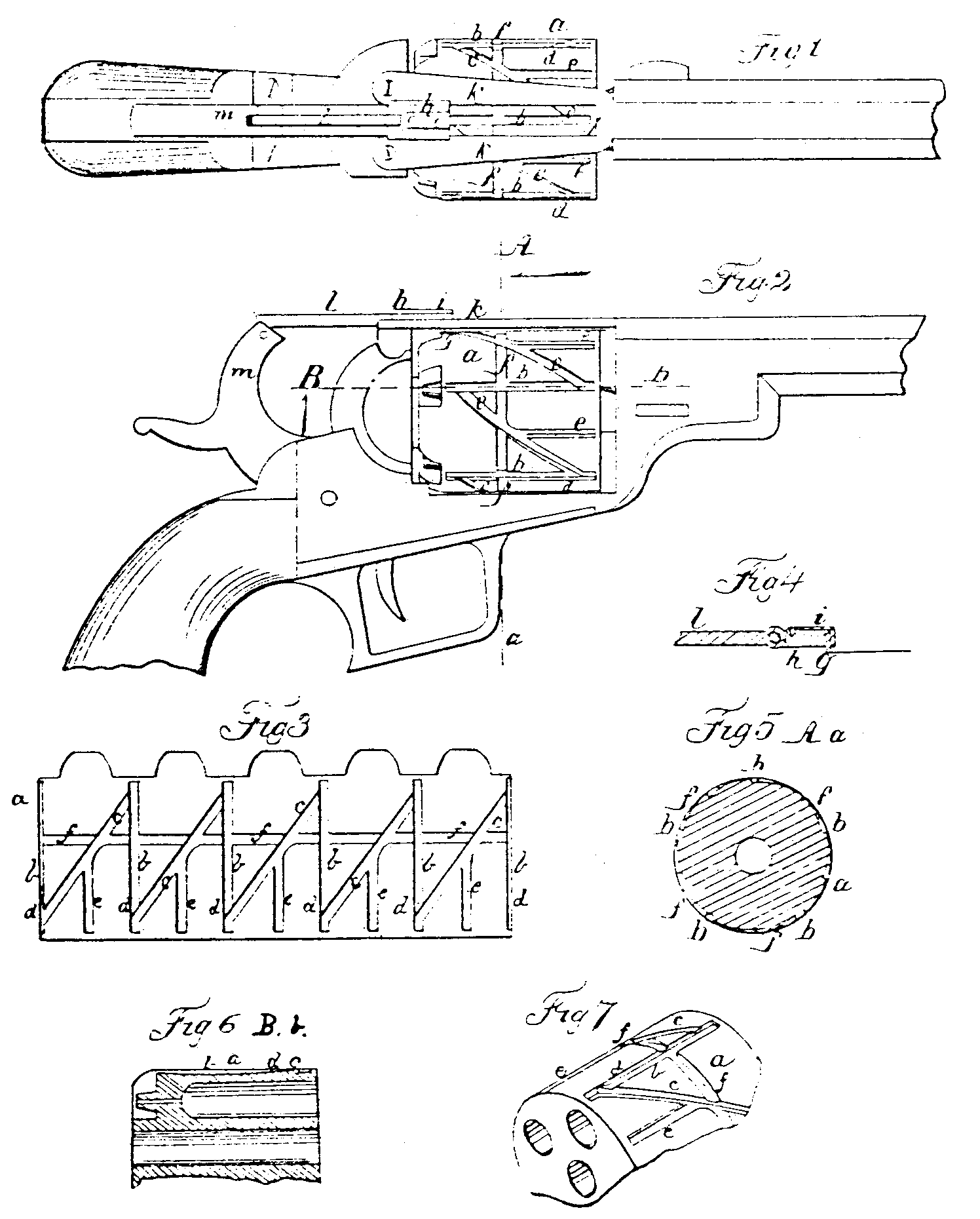
Figure 1 is a top view of a pistol on my improved plan; Fig. 2, a side elevation thereof; Fig. 3, a separate view of the periphery of the rotating breech developed; Fig. 4, a section of the slide and pin for rotating the breech; Figs, 5 and 6, sections of the rotating breech at the lines A a and B b of Fig. 2, and Fig. 7 a perspective view of a portion of the breech.
The same letters indicate like parts in all the figures.
My said invention relates to improvements on the method of rotating the many-chambered breech in fire-arms by a driving pin or bolt operated by the cock, or some part of the lock moving in unison with the cock, and sliding in a series of grooves cut in the periphery of the rotating breech, or some part connected with it, which grooves are so formed that in the act of firing the driving pin or bolt will run in one groove without turning the breech, thereby holding the particular chamber in line with the barrel, and in the act of cocking pass into and along another and diagonal groove, so formed as to rotate the breech and bring the next chamber of the breech in line with the barrel preparatory to another discharge; and my said invention consists in combining with such a series of grooves another series of shorter grooves connected with and running out of the diagonal grooves, and so located that after the breech has been rotated to bring the space be tween any two chambers in line with the barrel, by letting down the cock or hammer the pin or bolt shall run in one of the said short grooves and hold the breech in that position with the hammer of the cock resting on the barrel instead of on a nipple.
The object of this improvement is to avoid the danger of discharging a load by an accidental blow on the cock when resting on the nipple, such accidents having been of frequent occurrence with arms as formerly constructed; and my said invention also consists in making short lateral grooves running out of the diagonal grooves and in the direction of the rotation, the bottom of which are inclined and extend from the bottom of the diagonal grooves to near the surface, and so located that when the hammer is set at half-cock the said lateral grooves shall be in line with the pin or bolt, and thus admit of turning the breech by hand to any extent desired. Without this improvement it will be perceived that the breech could not be turned except by cocking and uncocking the hammer, which is frequently attended with inconvenience.
In the accompanying drawings the periphery of the rotating breech at is formed with a series of longitudinal grooves, b, one for each chamber, and extend nearly its whole length, and also with an equal number of diagonal grooves, c, each from near the forward end of one of the longitudinal grooves to near the rear end of the next. Each longitudinal groove b is formed with an inclined plane, d, just at its junction with the forward end of the diagonal groove, and the rear end of the diagonal groove is slightly inclined upward, are made of less depth than the longitudinal groove, and about midway between the longitudinal grooves are formed other or secondary longitudinal grooves, c, which extend forward from and run into the diagonal grooves.
At about the middle of the length of the rotating breech short inclined lateral grooves f are formed in the direction of the periphery, and extending from the bottom of the longitudinal grooves b and the diagonal grooves c to near the periphery.
There is a driving pin or bolt, g, fitted to a hole in a sliding block, h, and bearing against a spring, i, so that the driving-pin can rise when the tension of the spring is overcome. This pin or bolt is fitted to work in the grooves above described and pass over the inclined planes. The sliding block h is fitted to slide in ways made in a slot, j, formed in the upper plate, k, of the frame or lock-plate, and this block is connected by a joint-link, l, with the hammer or cock m.
From the foregoing it will be seen that in the act of cocking the sliding block, with its driving pin or bolt, will be drawn back, and the pin coming against the shoulder formed by the inclined planed will run into the diagonal groove, and therefore rotate the breech until it falls, thence into the next longitudinal groove b, and as there is one such longitudinal groove for each chamber properly located, the breech will by this means be turned to the required extent to bring a fresh chamber in line with the barrel. By the time the hammer is brought to a full-cock the spring-pin will have reached the rear part of the next longitudinal groove, which will lock and hold the breech in place and in line with the barrel; and as the diagonal groove at its connection with the rear end of the longitudinal groove is of less depth, in the act of discharging the driving pin or bolt will be prevented from running back in the diagonal groove, and will therefore run in the longitudinal groove, which being parallel with the bore of the chamber will keep it in a line with the barrel during the discharge. When the hammer is brought to the half-cock the driving pin or bolt is on a line with the literal inclined grooves f, so that the breech can be rotated by hand, the spring of the driving pin or bolt yielding to and following the inclined surfaces of these grooves. The bringing of the hammer to the half-cock turns the rotating breech about half the distance between two chambers, so that the driving pin or bolt will be in a line with one of the secondary longitudinal grooves, and then the hammer can be let down, the pin or bolt running forward in this groove to hold the breech in a position to have the hammer rest on the solid metal between two of the nipples. In this way it will be seen that the breech cannot be turned except by the act of cocking, and that in consequence the arm cannot be discharged by accidentally striking the hammer.
Instead of making the grooves for turning and holding the rotating breech on the periphery thereof, it will be obvious that, as an equivalent therefor, the said grooves may be made on a separate spindle projecting from the rear thereof, or placed below and geared with the rotating breech, that the motion given by the driving pin or bolt to the said spindle may be imparted to the rotating breech, and in such case the driving pin or bolt, instead of being connected with the head of the hammer, should be connected with some other part of the lock so as to be operated by the act of cocking. I have not described this modification as equally good with the first described, but simply to illustrate the changes which may be made within the range of my invention.
I do not claim as my invention the method of rotating the many-chambered breech in fire arms by a driving pin or bolt operated by the cock, or some part of the lock moving in unison with the cock, and sliding in a series of grooves cut in the periphery of the rotating breech or some part connected with it, which grooves are so formed that in the act of firing the driving pin or bolt will run in one groove without turning the breech, thereby holding the particular chamber in line with the barrel, and in the act of cocking pass into and along another and diagonal groove so formed as to rotate the breech and bring the next chamber of the breech in line with the barrel preparatory to another discharge, as this method has long been known, and, I have above stated, my invention consists in or relates to certain improvements which I have made therein.
What I claim as my invention, and desire to secure by Letters Patent, is—
1. Combining with the driving pin or bolt, and with the series of longitudinal and diagonal grooves for rotating the breech and holding each chamber in line during the discharge, substantially as described, the series of short longitudinal grooves for locking the rotating breech, so that the hammer can rest on the solid metal between two chambers instead of the nipple, substantially as described, to prevent accidental discharges.
2. In combination with the said driving pin or bolt and the series of long longitudinal and diagonal grooves, the lateral grooves or inclined planes, substantially as described, to admit of turning the breech by hand when the hammer is at half-cock, as set forth.
SAML. COIT.
Witnesses:
J. N. Stancliff,
E. K. Root.