
US 504154
UNITED STATES PATENT OFFICE.
PETER. H. FINNEGAN OF AUSTIN, ILLINOIS.
REVOLVER.
SPECIFICATION forming part of Letters Patent No. 504,154, dated August 29, 1898.
Application filed February 10, 1893, Serial No. 461,749, (No model.)
To all whom it may concern:
Be it known that I, PETER. H. FINNEGAN, a citizen of the United States, residing at Austin, in the county of Cook and State of Illinois, have invented new and useful Improvements in Revolving Fire-Arms, of which the following is a specification. This invention relates to fire-arms, and has for its object the improvement of the revolver construction described in Letters Patent No. 273,644, dated March 6, 1883, all as hereinafter set forth.
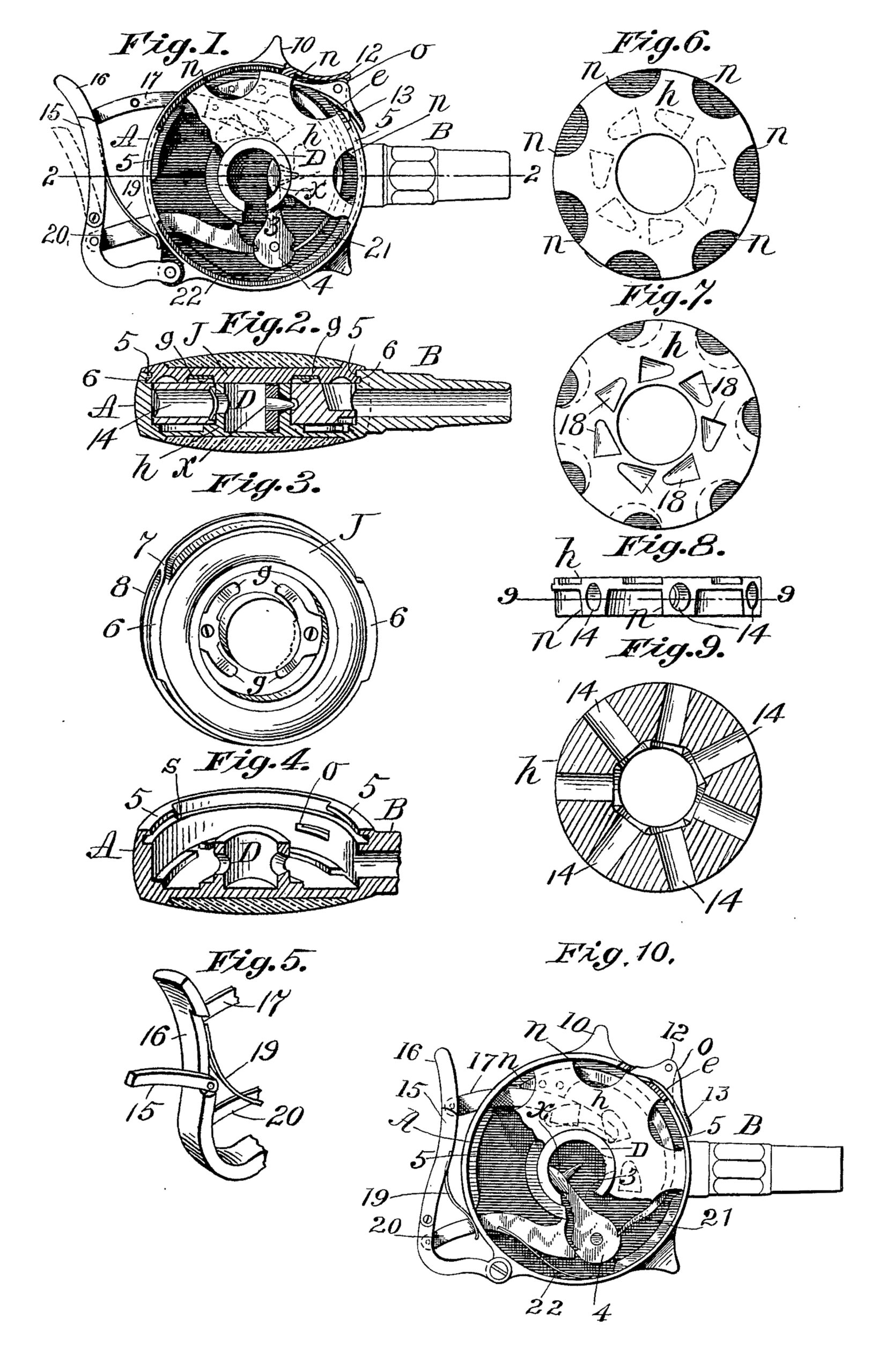
In the drawings forming part of this specification, Figure 1 is a side elevation, with cover removed, the case being shown partly in section, and the cylinder partly broken away. Fig. 2 is a section on line 2–2, Fig.1. Fig. 3 is a perspective view of the under side of the cover. Fig. 4 is a sectional perspective view of the case. Fig. 5 is a perspective view of a part of the trigger. Figs. 6 and 7 are plan views of opposite sides of the cylinder. Fig. 8 is an edge view of the cylinder. Fig. 9 is a section on line 9–9, Fig. 8. Fig. 10 is a similar view to Fig. 1, but illustrating the positions of the parts of the weapon when the hammer is at full cock.
The improvements in said revolver construction, hereinbelow described, relate to safety devices for preventing the arm from being fired inadvertently; to an improved manner of constructing the case, the barrel, and the breech-block, whereby increased strength and durability are secured, and the cost of construction is reduced, and whereby the grip of the arm is improved; to an improved construction of the devices for locking the cover to the case which contains the cylinder and other parts, –and to means connected with the arm, for ejecting shells from the cylinder.
In the drawings, A is the case containing certain operative parts of the arm, as below set forth; B, is the barrel, and D is the hollow, cylindrically formed breech-block on which the cylinder of the arm rotates. Said case, barrel, and breech-block, are integrally made from steel, iron, or other suitable metal. Said case has heretofore been made separate from the barrel, B, the latter being screwed into the border of the case; also, the breech-block, D, has heretofore been made separate from the case and united to the latter by screws, passing through one side of the case into one end of the block; but by changing the block by forming the longitudinal slot, 3, in it so that the nose, x, of the hammer, 4, can be introduced through the side of said block, to the working position shown in Fig. 1, the breech-block is made of one piece with the case, A, thereby effecting a considerable saving in construction. Likewise, by making the case and barrel of one piece, the weakness of a joint between said two pieces does not exist, the manipulation of, and work upon, two pieces is avoided and the work in finishing the same is rendered more economical. The said case has on its border, two inwardly overhanging lips or flanges, 5, 5, which, with two flange sections, 6, 6, on the border of the cover, J, Serve to secure said cover onto the case. To facilitate the quick removal of said cover from the case, the cover is provided with a cam-shaped formation, 7, at the end of one of said flanges, 6. When said cover is to be placed on the case, the two flanges, 6, on the cover are first brought between the flanges, 5, of the case. The cover is then turned, (bearing on the edge of the case) and the flanges, 6, run under the flanges, 5, thus locking the cover on. On turning the cover backward to unlock it, said cam, 7, strikes the end of one of said flanges, 5, and one edge of the cover is thereby lifted from the case and can be grasped by the fingers to lift it off. The thick end of said cam, 7, runs against one end of one of the flanges, 5, on the cover, and prevents the cover from being turned too far when locking it on. A stop pin, s, is placed under one of said flanges in the case when it is desired to limit the movement of the cover, J, in locking it. The cover, J, has two springs, g, g, on its inner side which bear frictionally against one side of the cylinder, h, when the cover is on the case, and prevent any by throw of the cylinder and assists in holding it closely on the breech block, D.
The case, A, has two finger-rests, 10, 12, on its border, one behind the other, in the forward one, 12, of which, preferably, is hung a safety latch, 13, one end thereof extending sufficiently through a slot, o, (see Fig. 4) in the side of the case to engage with the side of any one of the recesses, n, in the periphery of the cylinder, h. Said latch is held normally in the position shown in Fig. 1, by a suitable spring, e, placed under the outer end thereof: that is to say, in engagement with the cylinder, so that the arm cannot be discharged inadvertently. The outer end of said latch, 13, lies in convenient position to be pressed upon by the finger before firing, to disengage the cylinder and permit it to rotate to bring a cartridge opposite the barrel when the trigger is pressed. The finger rest, 10, serves as a rest for the latch finger when holding the arm, but not in a position to fire it.
The fire-arm, constructed as herein shown, has a cylinder, h, of disk form with cartridge chambers 14, extending radially from its axis, in which the cartridge shells are left after firing. To provide convenient means attached to the fire-arm for ejecting said shells from the cylinder, an ejector, 15, is pivoted by one end on one edge of the trigger, 16, and remains normally shut, as shown in Fig. 1, but when used as an ejector (the cylinder being taken out of the pistol-case) it is swung outwardly, as shown in Fig. 5, at right angles to the side of the trigger so that its free extremity may enter the chambers of the cylinder and eject the shells there from when the cylinder is forced against it. The trigger, 16, is hinged by one end to the border of the case, A, and has a pawl, 17, attached by one end thereto and its opposite end extends through the border of the case under the cylinder, h, and engages with any one of the recesses, 18, (see Fig. 7) in the under side of the cylinder and intermittently rotates the cylinder when the trigger, 16, is successively pressed upon. A spring, 19, retracts the trigger. The said trigger has an arm, 20, pivotally connected thereto near its hinged end which also enters the case, A, and engages with the notched edge of the hammer to swing that back for a blow against the cartridge while the cylinder is turning to bring one opposite the barrel B. A spring, 22, holds the end of arm 20, yieldingly against the edge of the hammer. A main-spring, 21, is secured to the bottom of the case, and has its free end engaging with a notch in the hammer.
It will be seen, from the foregoing description, that when the arm is properly held for firing, one finger presses the outer end of the latch, 13, and the trigger is then pressed forward, turning the cylinder on the breech piece, D, and operating the hammer, as described. The cover, J, is taken off to remove the cylinder and reload it, and upon replacing the cylinder the cover is locked on as described. A suitable perforation through the side of the breech-block permits the firing pin of the hammer to extend therethrough and strike the cartridge primer.
What I claim as my invention is–
1. In a revolving fire-arm of the class described, a cylindrical case, a cartridge-cylinder having an intermittent rotary movement in said case and having recesses in its periphery, combined with a safety-latch pivot ally hung on the border of said case, one end of which passes through said border, a spring under one end of said latch operating to retain the opposite end thereof normally in engagement with any one of said recesses, substantially as set forth.
2. In a revolving fire-arm of the class described, the cylinder-case having the integrally formed tubular breech-block centrally located therein, said block having a slot through its side extending from its extremity to its base whereby the nose of the hammer may be passed therethrough, substantially as set forth.
3. The case, A, having the finger-rests, 10, 12, on its border, one behind the other, combined with a safety-latch pivotally hung on the border of said case, and having one end opposite the forward side of said projection, 12, and its opposite end extending through said border in proximity to the periphery of the cylinder, h, said rear rest, 10, serving as an abutment for the finger for carrying the arm, thereby leaving the outer end of said latch free, combined and operating substantially as set forth.
4. In a revolving fire-arm, of the class described, means for locking and removing the
cover of the cylinder-case, consisting of sections of inwardly extending flanges, 5, 5, on the borders of said case, at the end of one of which flanges is a stop to arrest the circular movement of the case-cover, combined with a cover having sections of flanges thereon to engage under those of said case, one of said cover-flanges having a cam, 7, at one end to engage with one end of one of said case-flanges, thereby causing the cover to be lifted from the case when turned in one direction, substantially as set forth.
PETER. H. FINNEGAN.
Witnesses:
H. A. CHAPIN,
K. I. CLEMONS.