
US 166173
UNITED STATES PATENT OFFICE.
ROLLIN WHITE, OF LOWELL, MASSACHUSETTS.
IMPROVEMENT IN REVOLVING FIRE-ARMS.
Specification forming part of Letters Patent No. 166,173, dated July 27, 1875; application filed June 26, 1875.
To all whom it may concern:
Be it known that I, Rollin White, of Lowell, in the county of Middlesex and in the State of Massachusetts, have invented certain new and useful Improvements in Fire-Arms; and do hereby declare that the following is a full, clear, and exact description thereof, reference being had to the accompanying drawings, and to the letters of reference marked thereon, making a part of this specification.
My invention relates particularly to revolving fire-arms having a many-chambered cylinder rotated by the raising of the hammer. The object of the first part of my invention is to remove the old shells by the insertion of new cartridges at the other end of the cylinder or by the firing of said new cartridges; and to this end the nature of my invention consists in a cylinder for revolving fire-arms made wholly or in part reversible, so that new cartridges may be inserted in the opposite direction to that of the old shells. The second part of my invention has for its object to prevent the pawl from entering the ratchet until the locking-bolt has been first released; and this part of my invention consists in a peculiar construction of the pawl and locking-bolt, all as hereinafter more fully set forth.
In order to enable others skilled in the art to which my invention appertains to make and use the same, I will now proceed to describe its construction and operation, referring to the annexed drawing, in which—
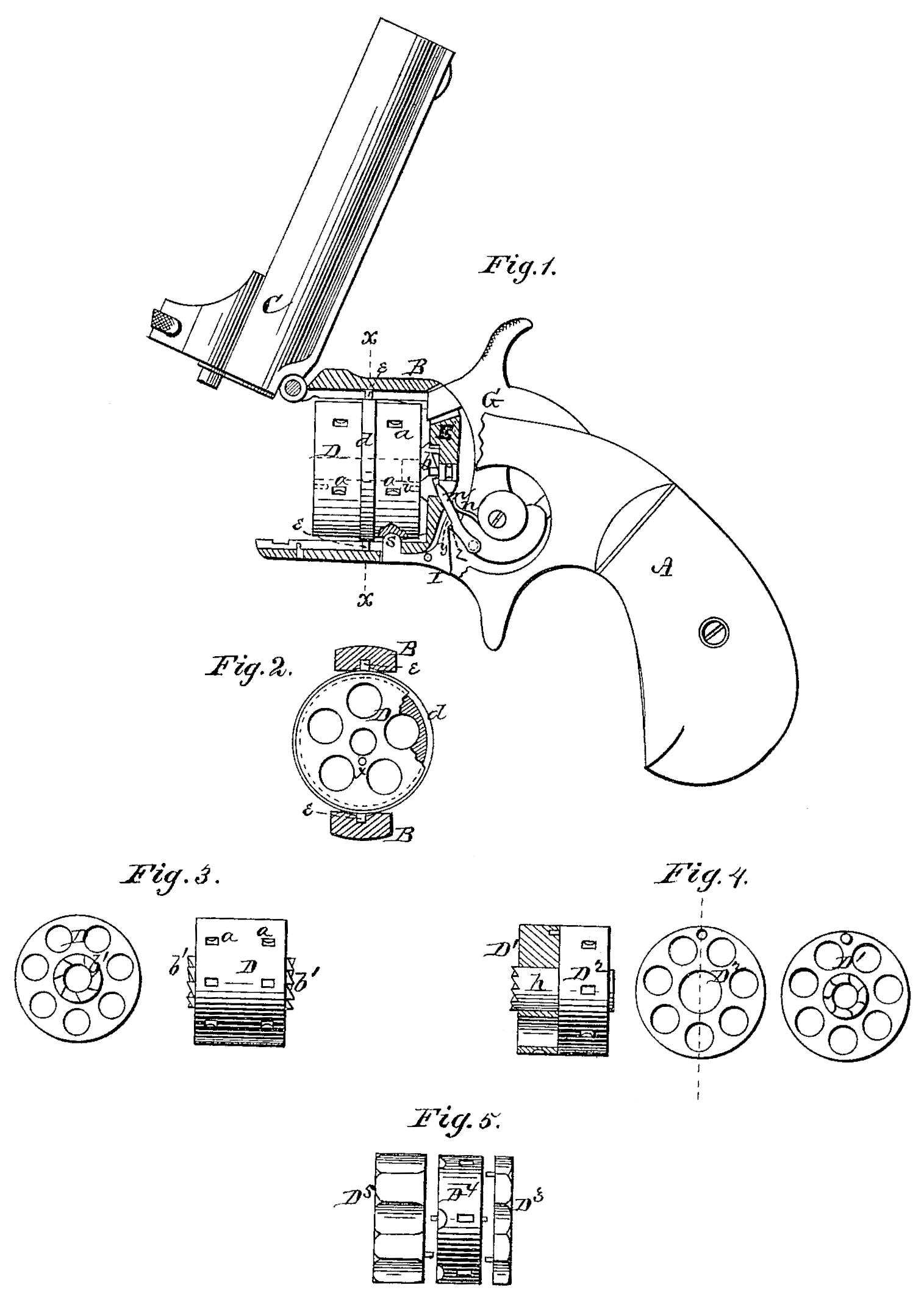
Figure 1 is a side view of a revolving fire-arm, with the lock-plate removed, the breech and frame being in section, and showing one form of my reversible cylinder. Fig. 2 is a transverse section of the same through the line x x, Fig. 1. Figs. 3, 4, and 5 show other forms of reversible cylinder.
A represents the butt, B the frame, and C the barrel, of a revolving fire-arm, the barrel being hinged in the usual manner to the frame. D represents the revolving cylinder, which is provided near each end with a series of recesses, a, on its outer side for the lock-bolt to enter into and hold the cylinder in position for firing. This cylinder is made reversible, so that the cartridges may be inserted from either end.
In Fig.1. I have shown the ratchet b arranged in the breech-plate E, and a pin, i, projecting from said ratchet entering a hole, x, in the end of the cylinder, so that the ratchet will rotate the same. A hole, x, is made in each end of the cylinder, so that either end may be placed on the ratchet. The cylinder D is formed with a circumferential groove in the center for the reception of a band, d, within which the cylinder is allowed to rotate. The band d is provided on opposite sides with pins or pivots e e, which enter longitudinal grooves in the top and bottom bars of the frame, and in said grooves are suitable stops to prevent the band and cylinder from being removed from the frame.
After all the chambers in the cylinder have been fired the barrel is thrown open in the usual manner. The cylinder is then moved outward until the pivots e are stopped, when the cylinder is swung around on said pivots and new cartridges inserted in the opposite end of the cylinder. The insertion of these new cartridges pushes out the old shells, and the cylinder is then put back in its place in a reversed position; or the old shells may be fired out with the new cartridges, in which case the bore of the barrel and chambers of the cylinder must be properly constructed to allow for the diameter of the cartridges. Where the cylinder revolves on a center pin or center pivots a ratchet, b’, is formed on each end of the cylinder, as shown in Fig. 3.
In the above I have described the cylinder in one piece, but it may be made in sections, and one section only reversible.
In Fig. 4 I have shown it made in two sections, D^1 and D^2, the outer section D^2 being formed with a center tube, h, on which the inner section D is placed, and the tube projecting through said inner section and formed with a ratchet on its projecting end. In this case the inner section D^1 is the part that is reversed, and when new cartridges are inserted on one slide the old shells are pushed out on the other. This section D should be of such thickness that the shell of the cartridge will project beyond the joint between the two sections, and thereby prevent the escape of gases through said joint. In Fig. 5 I have shown the cylinder made in three sections, D^3, D^4, and D^5, in which case it is the middle section D^4 only that is reversible, the inner section D^3 being swiveled or otherwise similarly attached to the breech-plate E, of which it forms a part. G represents the hammer, constructed in the usual manner, and having below its pivot-point a pawl, m, pivoted to it, which pawl is pressed forward by a spring, n, to engage with the ratchet and rotate the cylinder at the same time as the hammer is raised. s is the lock-bolt formed upon the front end of an L-shaped lever, I, pivoted in the lower part of the frame B. The upper rear end of the lock-bolt lever I is formed with a shoulder, y, and the ratchet-pawl m is formed on its under or front side, with a shoulder, Z, to catch on or abut against the shoulder on the lever, as shown in Fig. 1. When in the position shown in this figure the cylinder is locked by the bolts, and the hammer down. It will then be noticed that in raising the hammer the pawl m has a certain distance to travel before it enters the ratchet, and while it is traveling said distance the shoulder 2 of the pawl, pressing against the shoulder y of the lock-bolt lever I, turns said lever on its pivot, releasing the lock-bolts from the cylinder, so that, by the time the pawl commences to operate on the ratchet, the cylinder will be free to rotate.
When the hammer is let down the pawl passes over the inner end of the lock-bolt lever until the shoulders y z come against each other again.
Should it happen at any time that said shoulders are not engaged with each other and the hammer then raised, the lock-bolt lever will then remain unchanged, and the pawl will not enter the ratchet, as it is thrown backward from the same by the inner end of the lever.
Having thus fully described my invention, what I claim as new, and desire to secure by Letters Patent, is—
1. In a revolving fire-arm, a cylinder made wholly or in part reversible, for the insertion of cartridges in either end, as herein set forth.
2. The combination, in a revolving fire-arm, of the ratchet-pawl m, provided with the shoulder z, and the lock-bolt lever, provided with the shoulder y, to operate as and for the purposes herein set forth.
In testimony that I claim the foregoing I have hereunto set my hand this 16th day of June, 1875.
ROLLIN WHITE.
Witnesses:
J. N. Marshall,
Martin L. Hamblet.