
US 193367
UNITED STATES PATENT OFFICE.
SULLIVAN FOREHAND AND HENRY C. WADSWORTH, OF WORCESTER, MASSACHUSETTS,
IMPROVEMENT IN REVOLVING FIRE-ARMS.
Specification forming part of Letters Patent No.193,867, dated July 24, 1877; application filed August 23, 1875.
To all whom it may concern:
Be it known that we, Sullivan Forehand and Henry C. Wadsworth, both of the city and county of Worcester, and Commonwealth of Massachusetts, have invented certain new and useful.Improvements in Revolving Fire-Arms; and we do hereby declare that the following is a full, clear, and exact description of the same, reference being had to the accompanying drawings, forming a part of this specification, and in which—
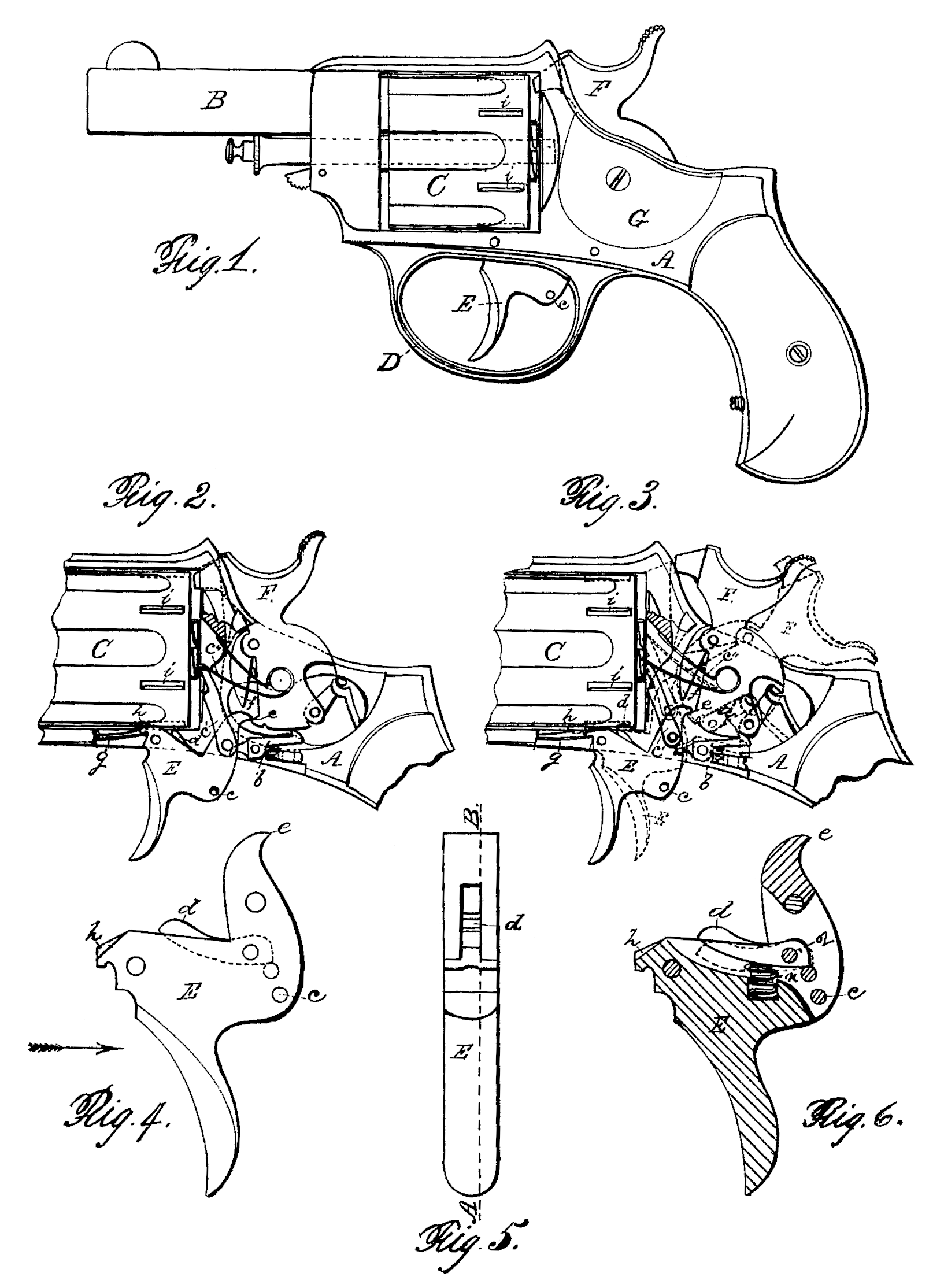
Figure 1 represents a side view of our improved revolving fire-arm. Fig. 2 represents a side view of the rear portion of the arm, with the side plate removed to illustrate and represent the position of the hammer after the arm has been discharged, and the manner in which the cylinder is locked and held in the said discharged position by a locking projection and a projecting part of the trigger. Fig. 3 represents a similar side view, the working parts, however, being shown in different positions in full and dotted lines— full lines showing the arm at half-cock, and dotted lines at full-cock, while the cylinder is shown unlocked in full lines, and locked by back-spring locking-bolt in dotted lines. Fig. 4 represents, upon an enlarged scale, the trigger detached. Fig. 5 represents, also upon an enlarged scale, an edge view of the trigger, looking in the direction indicated by the arrow, Fig. 4; and Fig. 6 represents, also upon an enlarged scale, a section on line A B, Fig. 5, showing very clearly the position of the back spring locking-bolt.
To enable those skilled in the art to which our invention belongs to make and use the same, we will proceed to describe it more in detail.
In the drawings, the part marked A represents the frame of the arm; B, the barrel; C, the chamber or revolving cylinder; D, the trigger-guard; E, the trigger; F, the hammer; and G, side plate to arm, held in place in the usual manner.
As our present improvements have special reference to a novel and special mode of locking and unlocking the cylinder at certain times, as will be hereinafter more fully explained, and of holding the hammer in a safe position while the arm is being loaded, the description will be confined mainly to the devices by which said results are obtained, since the other parts of the arm may be made in the usual or in any desired manner.
In the operation of loading the arm, the hammer is first drawn back, so as to allow catch b to spring into the half-cock or safety notch a, which places the arm in the proper position to load or unload the chambers. After having loaded the chambers the hammer is drawn back to full-cock, either by pulling on the trigger E or by drawing back the hammer F by the hand.
. In discharging the arm, the safety-catch b is unlocked from the safety-notch a by the pin c in the trigger E, lifting the forward end of the safety-catch b. At the same time the back-spring locking-bolt d in the trigger E locks the cylinder while the chamber is in line of discharge, and the point e of the trigger E. escapes the fly f, and allows the hammer F to spring forward and discharge the cartridge. Then the trigger-spring g forces the trigger E forward, and the projecting point, h on the forward end of the trigger E locks into the forward end of the bolt-slot i in the cylinder C, which also prevents the cylinder C from revolving when the hammer rests upon the exploded shell, or as in position shown in Figs. 1 and 2.
The cylinder is rotated by the hand or pawl c’, held in place by the pawl-spring c”. Locking-bolt d is hinged at 2 in the trigger E.
The front end of the back-locking bolt d is forced up to lock the cylinder at the proper time, as above described, by means of a spiral spring, n, fitted in a hole in the trigger. The safety-catch b is also held up by a proper spring.
Those skilled in the art will readily appreciate the value of our present improvements in revolving fire-arms, since by them the cylinder is securely locked by the trigger-bolt d when the arm is at full-cock, and at the discharge of the arm the projecting point h of the trigger again locking the cylinder, and when it is desired to load the arm the safety-catch b, holds the hammer securely in position.
Having described our improvements in revolving fire-arms, what we claim therein as new and of our invention, and desire to secure by Letters Patent, is—
The combination, with the cylinder C and hammer F, of trigger E, provided with locking projection h, trigger-point e, locking-bolt d, spring n, safety-catch b, and fly f, constructed and relatively arranged for operation substantially as and for the purposes shown and described.
SULLIVAN FOREHAND.
HENRY C. WADSWORTH.
Witnesses:
J. Nichols,
E. E. Moore.