
US 168562
UNITED STATES PATENT OFFICE.
WILLIAM. H. ELLIOT, OF NEW YORK, N.Y.
IMPROVEMENT IN REVOLVING FIRE-ARMS.
Specification forming part of Letters Patent No. 168,562, dated October 11, 1875; application filed September 9, 1875.
To all whom it may concern:
Be it known that I, Wm. H. Elliot, of the city, county, and State of New York, have invented a Revolving Fire-Arm, of which the following is a specification:
My invention refers particularly to that kind of arms known as revolving pistols, though in some of its features it is applicable to arms of any kind; and its principal object is to enable me to make a very compact and convenient revolving pocket-pistol of a large bore. The nature of my invention consists in a novel arrangement, construction, and operation of the revolving devices of the locking-bolt and of the main spring, all of which is fully set forth in the following specification and claims.
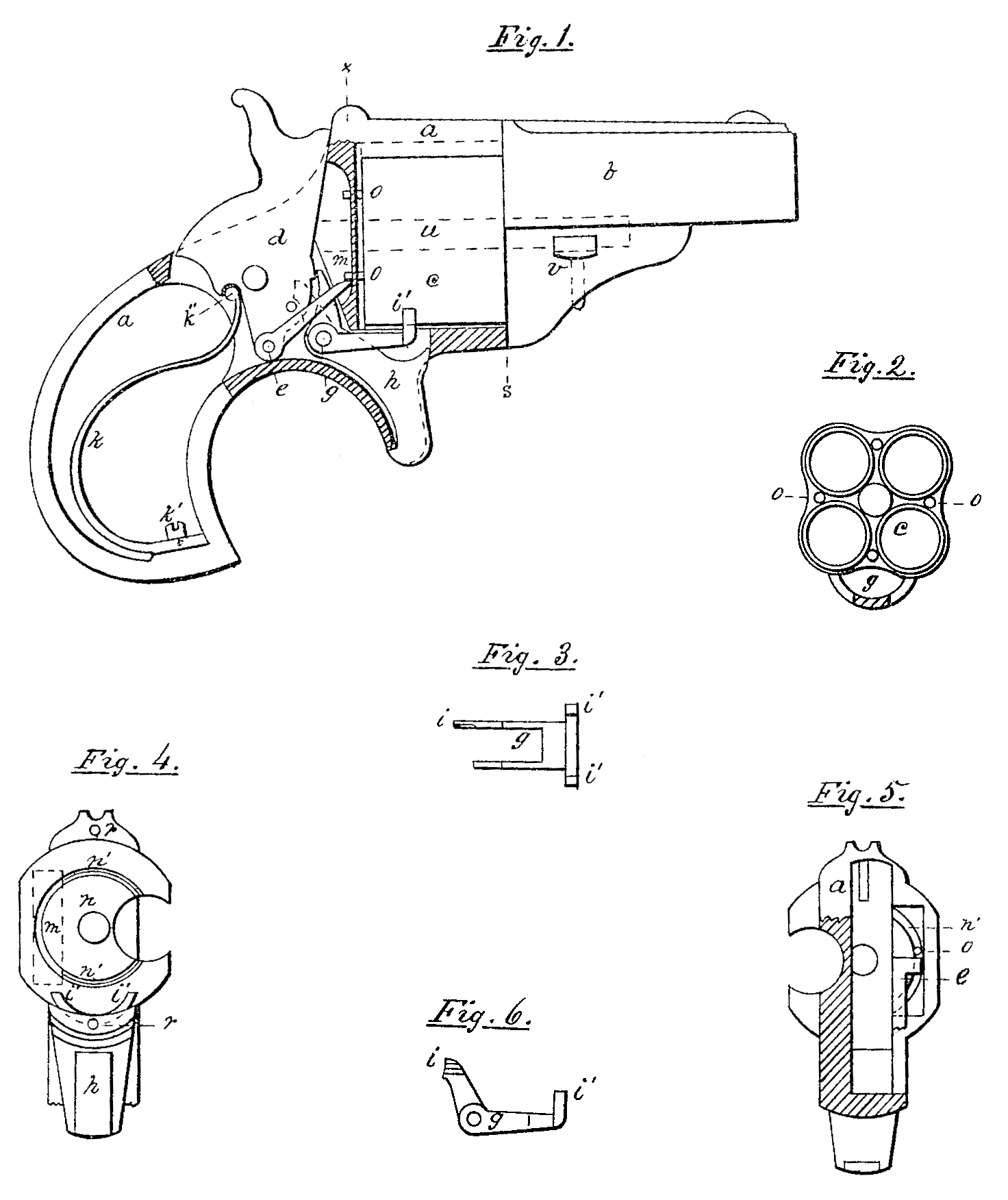
Figure I is an elevation of my improved arm, showing portions of the frame removed, so as to expose the limb-work. Fig. 2 is an elevation of the rear end of the cylinder, and also a section of the locking-bolt. Fig. 3 is a plan of the locking-bolt. Fig. 4 is an end elevation of the frame, with the barrel and cylinder removed. Fig. 5 is a vertical section of the frame at dotted line x, looking toward the barrel. Fig. 6 is an elevation of the locking-bolt.
a is the frame; b, the barrel; c, the cylinder; d, the hammer; e, the revolving pawl and its pivot; g, the locking-bolt and its pivot; h, trigger on the same pivot with the locking-bolt; i, the beveled end of the locking-bolt; i’, the extended arms of the locking-bolt, which embrace the chambers of the cylinder; k, mainspring; k’, fixed seat of the same on the frame; k”, fixed bearing of the mainspring in the hammer; m, cut on the back of the breech- plate for the revolving pawl; n, breech-plate; n’, groove in the face of the same; o, revolving pins or ratchet; r, dowel-pins, which form a slip-joint between the barrel and frame at lines; u, base-pin; v, key which holds the slip-joint together; x, line of section.
It has long been a desideratum by inventors to provide means of revolving the cylinder of a fire-arm by sure and practical means without increasing its diameter for the purpose of making room for the revolving devices, all of which I have accomplished by the following means: I put in or form upon the rear end of the cylinder the pins or projections o. These project about three-thirty- seconds of an inch beyond the heads of the cartridges into the breech-plate. To provide room for these pins I form a groove in the breech-plate of just sufficient depth to receive them. These pins are put into the solid metal of the cylinder between the chambers and outside side of the point, where the heads of the cartridges come nearest together, as shown in Fig. 2. Thus I have a ratchet so far from the center of the cylinder that it requires the whole backward sweep of the hammer to effect the revolution of the cylinder from one chamber to another, and it is therefore proportionably strong to overcome friction.
To facilitate the operation of the revolving pawl upon the ratchet-pins, I make a vertical cut, m, in the back of the breech-plate about one-fourth of an inch wide and three-fourths long, as shown in Figs. 1 and 5. The bottom of this cut is parallel with the face of the breech-plate, which is so thin at this point that the ratchet-pins project through it, and are operated upon by the revolving pawl behind it, so that notwithstanding the pawl operates upon the ratchet directly over the cartridges it cannot come in contact with them. The groove n’ being only one-sixteenth of an The groove in being only one-sixteenth of an inch in width the heads of pistol-cartridges are not forced into it, nor even strained, by the force of the gas. The end of the revolving pawl is broad enough to fill the cut m, and makes a direct vertical movement, while each ratchet-pin, as it comes around, slides back and forth across the end of the pawl.
By this arrangement of the revolving devices I can use a cylinder of four large chambers so close together that the heads of the cartridges will touch the base-pin, and the partitions between the chambers will be as thin as they can safely be. Such a cylinder should be fluted its entire length, as seen in Fig. 2, so that when turned to and locked in a middle position, as it should be when prepared for the pocket, it will occupy the least possible amount of space. A cylinder of this kind, when locked in position for firing, has one chamber above and one below; and to avoid making a cut into the metal of the cylinder over the chambers for the point of the locking-bolt, I employ a locking-bolt with two points sufficiently extended to embrace one of the chambers, as shown at i’ in Figs. 1 and 4. These points may be formed so as to take a more positive hold on the cylinder by fitting them to shallow cuts at each side of the chambers. When the cylinder is in the central position they rest upon two chambers at once, as shown in Fig. 2, and they hold it stationary.
My improved locking-bolt is operated in the usual way by a cam on the side of the hammer.
In my improved arm I employ a mainspring of peculiar construction, it being in the form of the letter S, and fastened at one end to the frame by a screw, and at the other end having a fixed bearing in the hammer. This spring gives off its force in two directions. One direction is parallel with a line drawn from the seat of the spring on the frame to its bearing in the hammer, and it is caused by a tendency of the spring to straighten out between its two points of attachment. This I call the parallel force. The other direction is lateral, and almost at right angles to the first, and is the result of the arrangement of the spring upon its seat, which gives it a tendency to sweep backward. This I call the lateral force. These two forces produce a resultant which has all the advantages that can be obtained by the use of a stirrup with ordinary springs—viz, freedom from friction with a light bearing upon the full-cock notch and a heavy bearing upon the safety-notch. The parallel force alone would hold the hammer up at full cock, but would throw it down with some force from the safety-notch, while the lateral force would act with great power on the full-cock notch, but would bear lightly upon the safety-notch. By my peculiar construction and application of the mainspring I combine these forces so as to produce the desired result. By the parallel force the free end of the spring is firmly held in its bearing in whatever position the hammer may be. No particular proportion between the upper and lower curves of the spring is necessary. The upper curve may be a very small one, but it must be sufficient to hold properly in its bearing in the hammer.
Having described my invention, what I desire to have secured to me by Letters Patent of the United States is—
1. In combination with the ratchet-pins o, the groove n’, when arranged in the breech-plate directly behind the chambers of the cylinder, substantially as and for the purpose specified.
2. The construction and operation of the ratchet-pins, breech-plate, and revolving pawl, whereby the revolving pawl operates upon the ratchet directly in the rear of the chambers, and behind the breech-plate, without coming in contact with the cartridges, substantially as specified.
3. The two extended points of the locking bolt, whereby that device embraces each one of the chambers as they come around to lock the cylinder, as herein set forth.
4. The S-shaped mainspring k, when immovably fixed upon its seat k’, and provided with a fixed partially-rotating bearing in the hammer, whereby it is made to give off a combined parallel and lateral force, substantially in the manner and for the purpose specified.
WM. H. ELLIOT.
Witnesses:
D. Lewis,
Richard W. Jones.