
US 100227
UNITED STATES PATENT OFFICE.
ROLLIN WHITE, OF LOWELL, MASSACHUSETTS,
IMPROVEMENT IN REVOLVERS.
Specification forming part of Letters Patent No. 100,227, dated February 22, 1870.
To all whom it may concern:
Be it known that I, Rollin White, of Lowell, in the State of Massachusetts, have invented certain new and useful Improvements in Pistols; and I do hereby declare that the following is a full and exact description there of, reference being had to the accompanying drawings, making part of this application.
My invention relates more particularly to certain new and useful improvements in that kind of pistols composed of a stationary barrel and revolving cylinder having its chambers bored through, though portions of my invention are adapted as well to other kinds of fire arms.
Previous to my present invention this kind of pistol has involved the objection that no larger cartridge could be used in it than the size adapted to the chambers of its cylinder, which is necessarily small.
To overcome this objection is one object of the first part of my invention, which consists in the employment, in connection with the ordinary stationary barrel and revolving cylinder, of one or more supplementary barrels having the bore extended through, and adapted to receive and fire a larger cartridge than that used in the cylinder, and so arranged that it can be conveniently and rapidly fired by means of the same cartridge-exploding device, as will be presently more fully explained; and my invention further consists in the novel arrangement of a firing-pin in and extending through the axis of the cylinder, as hereinafter described, and in the construction and arrangement of the hammer in relation thereto.
My invention further consists in the relative position of the tumbler, sear, and trigger, and their arrangement within the frame, as fully shown and hereinafter described; also, in the combination of the hammer and tumbler with the mainspring and sear, under the arrangement shown, whereby all increasing power is exerted on the hammer by the mainspring, and a highly-sensitive trigger is obtained, as hereinafter more fully set forth.
To enable those skilled in the art to make and use my invention, I will proceed to describe the several features of my said invention more particularly, referring by letters to the accompanying drawings, in which—
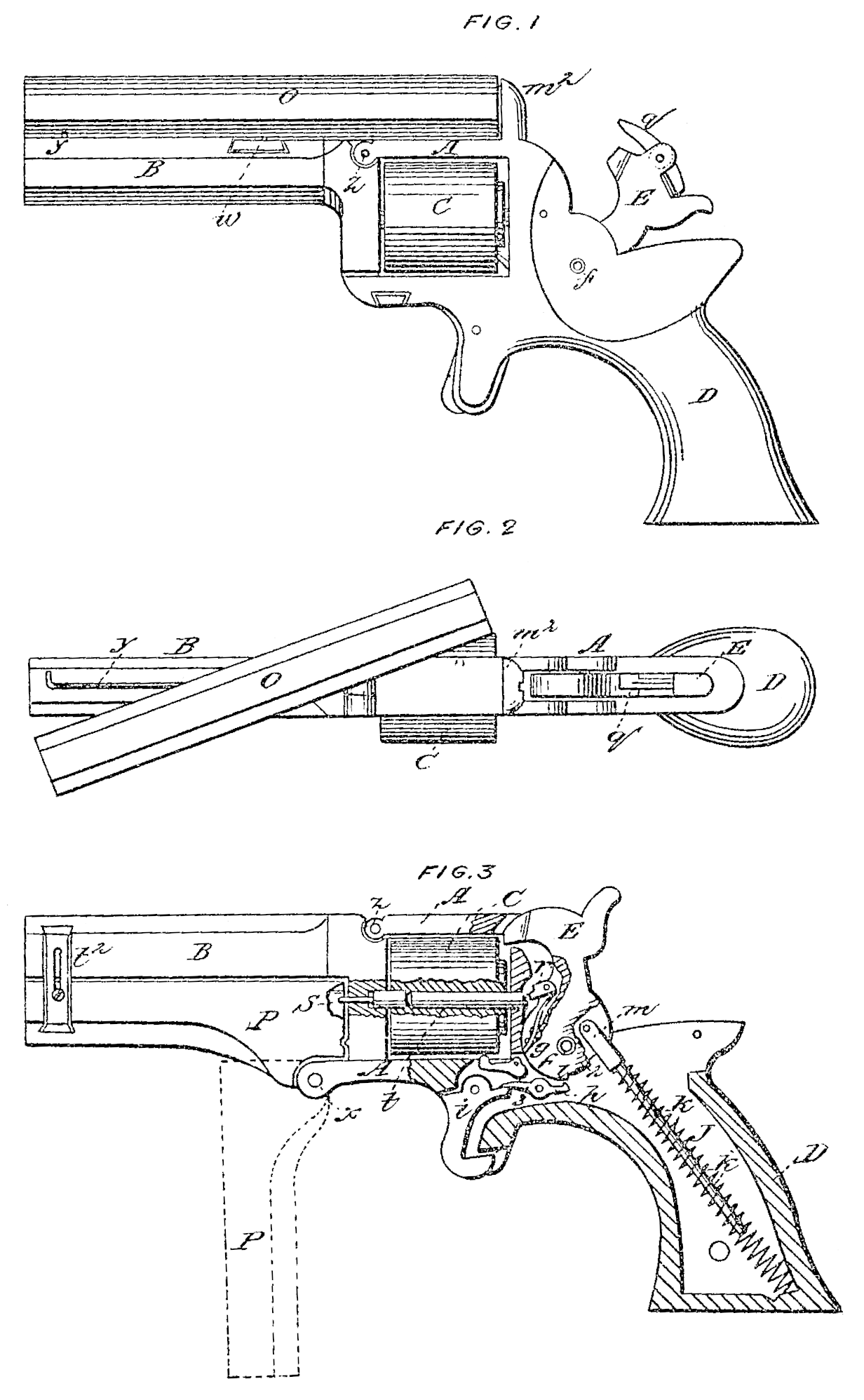
Figure 1 is an elevation of a repealing-pistol embracing my invention. Fig.2 is a top view of the same. Fig. 3 is a sectional elevation, showing a different mode of applying the auxiliary barrel.
In the several figures the same letter of reference denotes the same part.
A is the frame, B the barrel, C the cylinder, and D the stock, of the pistol.
E is the hammer, which is hung on a stud at f to turn in the usual manner, and is formed with a tumbler, g, into the notches 1 2 of which catches the rear end of the sear h, which is pivoted at 3, and is operated upon at its for ward end by the trigger i. Within the stock D is arranged a spiral spring, J, which constitutes the mainspring of the arm, and within which is arranged a rod or pin, k, pivoted or coupled at in to the hammer.
L is the bolt. O and P are auxiliary barrels, and q r firing-dogs attached to the hammer, and S firing-pin to lower auxiliary barrel. t is the base-pin, on which the cylinder turns, actuated by a hand or pawl, attached to the hammer, working in the ratchet in the usual manner. The lower barrel, P, is arranged to swing down on a pivot x a, and is secured in position by means of a slide-catch, t^2. The top barrel, O, may be applied by moans of a shoe, w, adapted. to slide into a dovetail seat cut in top of barrel B, upon which shoe it may turn, as illustrated, and may be secured in position by means of a spring-catch, y. Although both of the auxiliary barrels O and P can be applied at the same time, still I propose to construct the pistol and adapt it to the employment of one or the other of such barrels— as, for instance, for the use of a top auxiliary barrel, as illustrated at Figs. 1, 2, or for the use of a lower auxiliary barrel, as seen at Fig. 3.
I will briefly explain the operation of my improved pistol as illustrated at Fig. 3, and afterward describe it in the modification illustrated at Figs, 1 and 2.
When the barrel P is to be loaded the catch t^2 is pushed down and the barrel swung down into position, (shown by red lines, Fig. 3,) the cartridge is inserted and the barrel closed up and secured by said catch, when by cocking the hammer and pulling the trigger the cartridge will be exploded, the explosion of the cartridge being effected by the firing-pin S, which is forced forward by the sliding base-pin t, which is struck at its rear end by the dog r, attached to the hammer. The said dog r and the hammer are so relatively arranged that the former strikes and rests upon the base-pin it before the hammer can come in contact with the cartridges of the cylinder C; but when it is desired to use the cartridges in said cylinder the dog r is folded it, as shown by red lines, when the hammer will be free to descend into the cartridges of the cylinder and explode them. The hammer is also held tap sufficiently by the dog ‘ during the use of the barrel P to prevent the operation of the pawl in the ratchet of the cylinder, and consequently the latter will maintain a fixed condition as long as the dog r is in position to fire the cartridges of the auxiliary barrel P; and when said dog is folded up so that the revolving cylinder can be used, then said dog will not operate the sliding base-pin, and a cartridge in barrel P will not be exploded.
In lieu of the pin S and sliding base-pint, the latte could be made stationary and hollow and a firing-pin run through it. Of course many modifications of detail may be suggested and employed to effect the mode of operation described.
If deemed expedient, the connection of the swinging barrel P with, the frame A may be so made that the barrel can be detached from and coupled to the frame at pleasure.
It will be understood that when the cylinder is used it is loaded in the usual manner, the barrel B being pivoted at Z, and adapted to swing up to permit the removal of the cylinder for loading.
By having the mainspring made as shown and described in lieu of having a leaf-spring, or one acting in a curved line, the hammer is actuated with more force and effectiveness nearest its time of striking the cartridge, and, being brought to nearly a dead-center at the full-cock, is pressed forward very slightly during its start, which is of great advantage, since, in consequence of the spring J and its rod k being brought into line nearly with the axis of the hammer at the full-cock, the tendency of the spring to move the hammer at the start is very slight, and consequently there is no pull or strain on the sear, and it can be relieved entirely from the hammer and let it off by means of the most delicate touch upon the trigger, and with little strain or wear on the cock-notch.
Although I have shown a rod, k, arranged within the spring J, and coupled to the hammer, it will be understood that the wire of the spring itself could be connected to the hammer; or, in lieu of the simple spiral spring, a volute spring could be employed; and it will be seen that by the use thus of a spring acting in a right line I am enabled to accommodate the mainspring in a small hole in the stock, and can consequently make the latter much smaller and of more desirable shape than I could with the use of the ordinary kind of mainspring.
By arranging the sear, as shown, to take hold in the lower back part of the hammer and extending it forward to the trigger, with the latter acting on its forward end, I am enabled to place the trigger and rest for the forefinger farther forward and in a much more comfortable and desirable position than that in which the trigger can be placed (relatively to the stock) in pistols heretofore made; and by thus carrying forward that portion of the frame in which the trigger is located and arranging the bolt as shown I am enabled to have the latter work under the cylinder and inclosed, and at the same time make that part of the frame forward of the trigger, so thin as to bring the forefinger close up under the cylinder in grasping the pistol.
The sear is so pivoted relatively to the location and shape of the cock-notch of the hammer as to move into and out of said notch without moving the hammer— that is to say, the pivot of the sear is so placed as to cause the face of each portion of the sear to move in an arc about coincident with the short straight line (or arc) of the cock-notch, whereby the motion of the sear into and out of said notch in the hammer may be effected without moving the hammer at all.
If it be desired to employ the auxiliary barrel on top, as shown at Fig. 1, the breech should be extended up, as seen at m^2, and perforated for the passage of the dog g, and the barrel B recessed out on top to receive the shoe w, or some other convenient means adopted fur the attachment of the said barrel.
In lieu of having the barrel O swing on a pivot it may be arranged to swing from one end, or to slide forward from the breech for the insertion and extraction of the cartridge-cases, as may a deemed expedient.
It will be evident to those skilled in the art that there are many different ways of carrying out the several features of my invention, and that some one or more characteristic features of my several improvements may be used to great advantage without using the whole of my invention.
It will be understood that the supplementary barrel I may be placed above, beneath, at the side of, or at any suitable place relative to the cylinder, so that it is arranged in front thereof.
My improvement may be readily adapted to the ordinary style of pistol now it common use simply by a slight modification of the center-pinto make it a firing-pin, as will readily be seen; and by my arrangement of the supple-mental barrel at any place in front of the cylinder I am enabled to use a cylinder of the ordinary size, or, in other words, I am not compelled to use an enlarged cylinder, and can add a supplemental barrel by a slight modification to the ordinary pistol by placing it in front or on the outside of the cylinder.
What I therefore claim, and desire to secure by Letters Patent, is—
1. The supplemental barrel P, when the same is arranged so that its breech is in front of the cylinder, substantially as and for the purposes set forth.
2. The combination, with a revolving fire-arm, of a supplemental barrel, when the same is arranged above the cylinder and ordinary barrel, as shown and described.
3. The combination, with the auxiliary barrel P of a revolving fire-arm, of a firing-pin arranged to work through the cylinder, as set forth.
4. The combination, with the hammer of a fire-arm provided with an adjustable beak or projection, of the firing-pin arranged and operating as set forth.
5. The combination and relative arrangement of the tumbler, sear, and trigger, where by the sear can play into and out of the tumbler-catches, as described, and the trigger is located forward of the rear end of the cylinder, as shown.
6. The arrangement of the mainspring J within the stock and in relation to the hammer E, so that when the hammer is cocked the pressure of the mainspring will be mainly on the pivot thereof, instead of mainly in opposition to the sear, as and for the purposes specified.
In testimony whereof I have hereunto set my hand and seal this 26th day of February, 1868.
ROLLIN WHITE. [L.S.]
In presence of—
John B. McAlvin,
Thos.G. Gewith.