
US 104636
UNITED STATES PATENT OFFICE.
WILLIAM. I. PAGE, OF BOSTON, MASSACHUSETTS, ASSIGNOR TO HIMSELF AND CHARLES E. ROBINSON, OF SAME PLACE.
IMPROVEMENT IN REVOLVING FIRE-ARMS.
Specification forming part of Letters Patent No. 104,636, dated June 21, 1870.
To all whom it may concern:
Be it known that I, William. I. Page, of Boston, in the county of Suffolk and State of Massachusetts, have invented a new and useful or Improved Revolver; and I do hereby declare the same to be fully described in the following specification and represented in the accompanying drawings.
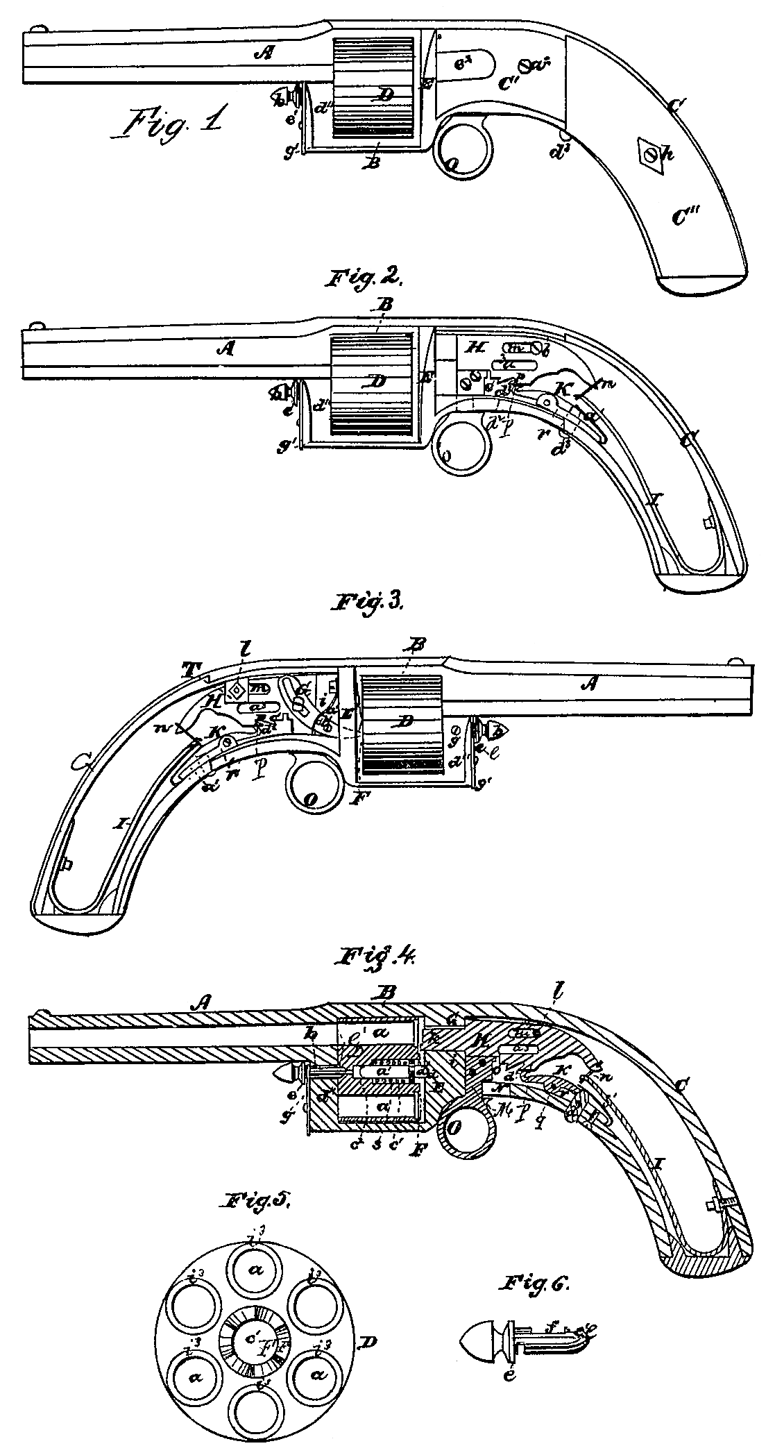
Of the said drawings, Figure 1 denotes a side view of the said revolver. Figs, 2 and 3 are side elevations of the same with the lateral plates of the rear portion removed in order to more clearly exhibit the parts of the lock. Fig. 4 is a vertical, central, and longitudinal section of the same. Fig. 5 is a rear end view of the cylinder, Fig. 6 is a side view of the bolt or safety-pivot, to be hereinafter described.
My invention has reference to that class of revolving fire-arms in which the cocking of the hammer and the rotating of the cylinder so as to bring its chambers successively in position for being fired are effected by a single movement or retraction of the hammer; and my invention consists in a peculiar mode of mounting and securing the chambered cylinder with in its carrier, whereby the cylinder cannot only be either readily applied to or removed from the carrier, as circumstances may require, but its chambers be caused to maintain a close or gastight connection with the bore of the barrel during a discharge of the piece; also, in the peculiar construction and relative arrangement of the several parts of the lock, whereby great simplicity, strength, and compactness are attained.
In the said drawings, A denotes the barrel of the revolver, B the cylinder chamber, or carrier, and C the main metallic portion of the handle, all the said parts being cast or formed of one piece of metal.
C’ C’ are two metallic plates, which are disposed on opposite sides of the part C.
C” C” are two wooden plates, which cover the sides of the mainspring, and are also connected with the part C by means of a screw, h. The drawings show but one of the plates, C’ or C”.
D is a cylinder, which is provided with a series of chambers, a, arranged in a circle near its periphery, the said chambers extending entirely through the cylinder. If desirable, the near portion of each of the said charge-chambers may be countersunk or enlarged to receive the flanged heads of metallic cartridges or “fixed ammunition,” and thereby allow the cylinder to fit closely to the breech-plate E. The said cylinder is mounted or supported within its chamber by means of a spring-arbor, a’, which is formed and applied thereto as shown in Fig. 4. The said arbor has a spring, s, wound helically about it, one end of which rests against a shoulder formed on the arbor and the other against the lower end of the spring-chamber c’, which is an enlargement of the arbor-cavity c^2, formed axially in the chamber. The conical or projecting end d of the said arbor enters a shallow socket formed in the front face of the breech-plate E, as shown in Fig. 4. Furthermore, the said arbor is so applied to its chamber as to permit the former to slide entirely within the latter while the cylinder is being either introduced into or removed from its chamber. On the said arbor, or axis the cylinder can be readily revolved by means of the rotating mechanism, to be hereinafter described.
In order to prevent accidental disengagement of the cylinder from its chamber by hard or rough usage, I apply to the outer end of such cylinder a safety-pivot or bolt, b, which passes through one of the walls d’ of the cylinder-chamber B and enters a socket, d^2, made in the end of the cylinder. This pivot, while it allows the cylinder to freely revolve, serves to maintain it securely in its chamber. Furthermore, the said pivot or bolt is provided with an annular shoulder, e, which determines the distance its conical end shall enter the cylinder. The said bolt or pivot is prevented from slipping out of its cavity by means of a screw, f, Whose point extends into a long slot, f, made in the shank of the pivot, the inner end of the said bolt, or pivot, while within the cylinder being maintained thereon by a turn-button, g^2, which enters a notch cut transversely in the shank of the pivot. By turning back the button g’ the pivot or bolt may be readily with drawn from the cylinder and the latter be easily detached from or applied to its chamber by simply grasping the cylinder between the thumb and forefinger and pressing against the cylinder either with the thumb or finger, as circumstances may require.
By mounting the cylinder upon the spring arbor, as set forth, the cylinder can not only be made of nearly the same length as its chamber, but be readily removed from or applied to its chamber, the spring serving also to maintain a close connection between the bores of the charge-chambers and the bore of the barrel when they are brought into coincidence for being fired.
The mechanism for rotating the cylinder the proper distance to bring each of its chambers successively into coincidence with the bore of the barrel consists of a ratchet-wheel, F, arranged axially on the rear end of the cylinder, and a curved traversing lever or pawl, G, which is pivoted to a projection, i, extending back of the breech-plate, as seen in Fig. 3, the rear end of such lever being pivoted to the slider H in such position that when the slider is drawn back so as to bring the hammer or slider E to a full-cock the front or beaked end of the said lever, operating on the teeth of the ratchet, shall give to the cylinder, the desired amount or rotation. On the slider being impelled forward the front end of the lever will be withdrawn; and will be forced downward the requisite distance to take into the next tooth of the ratchet when the hammer is next retracted or set at cock.
a’ is a spring, one end of which is attached to the rear part of the breech-plate E, and has its free end resting against a stud, b’, projecting from the lever G, as shown in Fig. 3, the object of such spring being to maintain the beak or front of the lever G in connection with its ratchet while the hammer is being cocked and the piece is being discharged. The said slider carries on its front end, a percussion pin or piercer, k, which works through a slot or hole, o, made through the projection i and the breech-plate E. This piercer may be so arranged as to impinge against the cartridge at any desired part of its head. In the present instance it is so disposed as to strike the cartridge upon its lower edge. The said hammer slides back and forth in a direct line, being guided in its movements by the slot o, before mentioned, and a stud, l, (extended from the projection T,) which works within an elongated slot, m, formed in the slider. To the rear end of the said slider one end of the mainspring I is attached by means of a loop, m, the other end thereof being affixed to part C, as seen in Figs. 2 and 3.
To one side of the slider H an arm, M, is attached, and extends down through a slot, N, made through the frame C, and carries on its lower end a finger-loop, o, by which the said slider or hammer can be set at either half or full cock, as may be desired
K is a curved lever, which constitutes both a catch-dog and trigger, the same having a hook, d, formed on its front end to engage with two notches, o p, disposed on the under inclined surface of the slider. One of the said notches, p is formed of a peculiar shape— viz with a sharp acute angle— so that when the hook of the dog is within such the piece cannot be discharged by means of the trigger. The lever K turns freely on a pin or stud, q, supported in projections from the frame C. The hook or catch of the dog is kept in engagement with the notches o or p by means of a springs. The rear end of the said lever K is provided with a short stud or cylinder, d^2, which extends there from at right angles and projects through a hole made in the under part of the frame C, as shown in Fig. 4, such stud forming a trigger or device for releasing the hammer from the action of the dog.
On one side of the revolver a chamber or cavity, e’, is made, such chamber being of sufficient size to receive a cartridge suited to the bore of the charge-chambers. This chamber extends through the breech-plate, so as to communicate with the chambers of the cylinder, and thus affords a means by which the cylinder may be charged without removal thereof, should it be desirable.
A fire-arm constructed in my improved manner possesses several important advantages. It is compact, simple, and strong, and little liable to get out of order. Its cylinder can be readily taken out of its chamber and easily applied thereto. The lock also is simple, and effective, the hammer thereof moving in a straight line.
Having described my invention, what F claim. is as follows:
1. The combination of a chambered cylinder mounted upon a spring-arbor, in manner as described, with the safety-pivot or bolt b, constructed, arranged, and applied thereto and so as to operate there with as and for the purpose set forth.
2. The relative arrangement, of the several parts of the lock, substantially as described and represented.
WILLIAM. I. PAGE.
Witnesses:
F.P. Hale,
Chas. E, Robinson.