
US 46023
UNITED STATES PATENT OFFICE.
REUBEN H. PLASS, OF NEW YORK, N.Y.
IMPROVEMENT IN REVOLVING FIRE-ARMS.
Specification forming part of Letters Patent No. 46,023, dated January 24, 1865.
To all whom it may concern:
Be it known that I, Reuben H. Plass, of the city and county of New York, in the State of New York, have invented a certain new and useful Improvement in Revolving Fire-Arms; and I do hereby declare that the following is a full and exact description of the construction and operation of the same, reference being had to the accompanying drawings, which form a part of this specification.
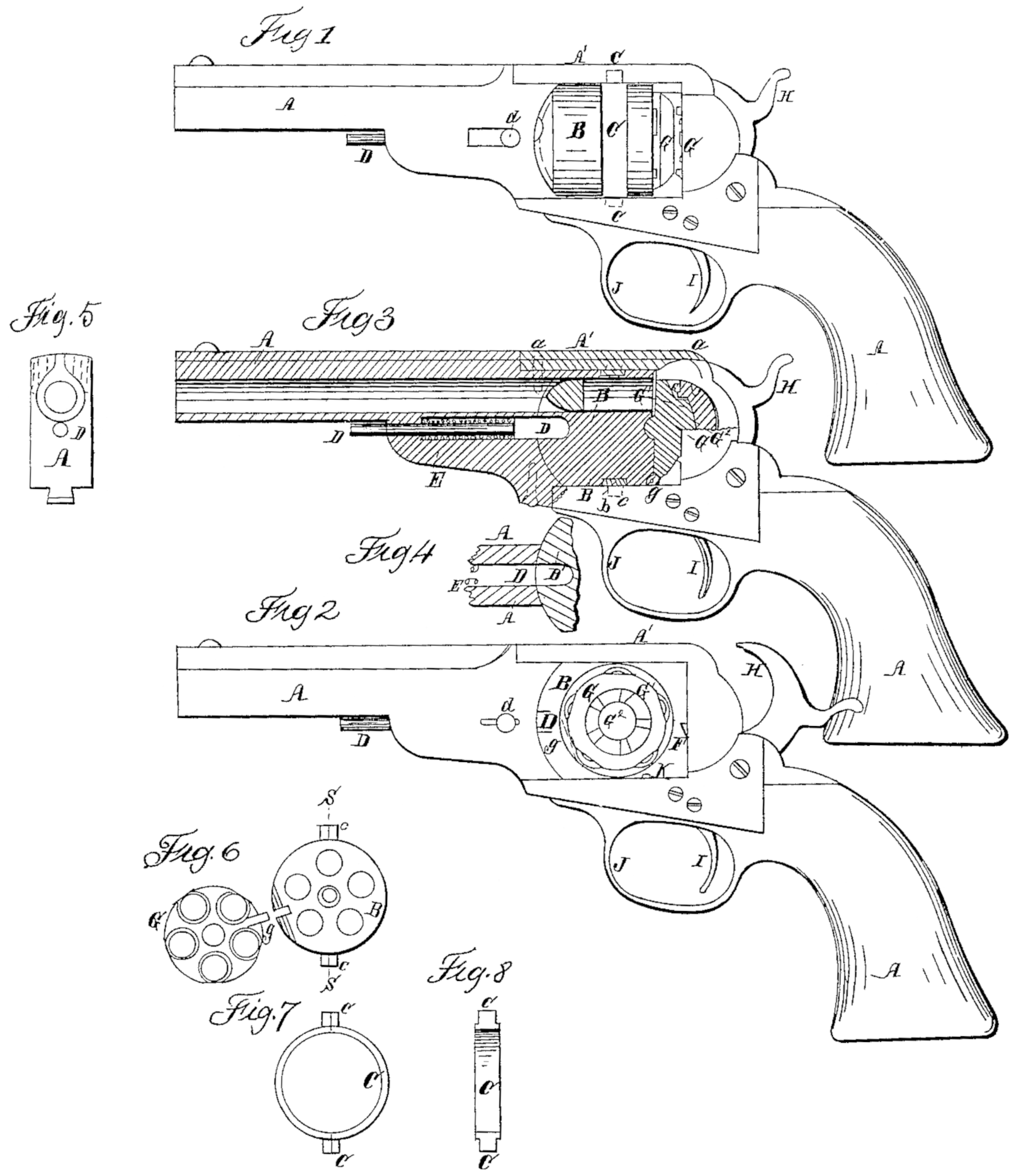
Figure 1 is a side elevation, showing the parts in position for use. Fig. 2 is a corresponding view, showing the parts in position for loading. Fig. 3 is a central longitudinal section. Fig. 4 is a horizontal section of the part immediately adjacent to the front end of the chambered cylinder, and shows the cavity in which it fits. Fig. 5isa front view of a portion. Fig. 6 represents the rear end of the chambered cylinder with the hinged plate which covers it. Fig. 7 represents the trunnion-ring in which the revolving cylinder turns. Fig. 8 is a section of the latter on the line S S in Fig. 6.
Similar letters of reference indicate like parts in all the drawings.
Tints are employed merely to distinguish parts, and do not indicate the material used, which may be the same as is ordinarily employed.
My invention is applicable to pistols and to arms of all kinds. I have represented it applied to a pistol, and shall so describe it; but it will be understood that muskets and rifles, carbines, &c., of the several different varieties may be correspondingly made and operated. My pistol is of the same class as Colonel Colt’s well-known revolvers, a number of cartridges being placed in a revolving part and successively discharged through a single barrel.
My invention relates to the construction and operation of the revolving part, and of the parts immediately connected therewith.
It consists in mounting the revolving part in another part, which is adapted to revolve, or to partially revolve, on an axis transverse to the other, and in certain modifications of the several parts of the pistol, to enable the pistol to be conveniently freed from the remains of the former cartridge, if any, and supplied with new ones, while the cylinder is turned out of its ordinary position by the revolution or partial revolution of this secondary part with its contents.
To enable others skilled in the art to make and use my invention, I will proceed to describe its construction and operation by the aid of the drawings and letters of reference marked thereon.
A is the stationary single barrel and the rigidly-connected parts of my pistol.
B is the revolving cylinder, and C is the surrounding part, made in the form of a ring in two parts, or halves, fitting into a groove, b, in the revolving cylinder B. Two trunnions, c c, are formed in the ring C at the points where the halves of Care joined. These trunnions are supported in bearings formed in the fixed part A. of the pistol, and allow the ring C and its contents to be turned on these trunnions. The axis of the trunnions are vertical when the pistol is held in its ordinary leveled position.
The part A’ of the stock may be removed by unscrewing the screws a, to allow the ring C and its contents to be taken out and replaced When required for cleaning or repairs.
The front end of the revolving cylinder B is spherical, or rather its surface coincides with that of a sphere, the center of which sphere is the center of the trunnion-ring C. The adjacent surfaces of the fixed portion A are correspondingly formed, so as to fit nicely together. D is a sliding pin with a rounded end, adapted to traverse to a limited extent in a line parallel to the barrel A, and E is a coiled spring, which impels the sliding pin rearward, so as to press into or against the revolving part B.
A cavity, B’, is provided in the front end of the revolving part B, which, when the revolving part Bis in position for use, receives the rear end of the sliding pin D, so as to confine the revolving part with its axis parallel to the axis of the barrel to leave it free to be revolved within the trunnion-ring C. The sliding pin D may be pushed forward by applying the thumb to the knob d, which protrudes through the slot in the side of the fixed part A, as indicated.
G is a rear plate hinged to the revolving part Bat the point g. It is adapted to cover the rear end of the chambers in the revolving part, and also to receive on its toothed surface G’ the action of a suitable paw), (represented by Fin Fig. 2,) which is connected with the works of the lock, so as to rotate the revolving part B at the proper time, according as the lock is operated.
K is a dog adapted to enter recesses in the revolving part and hold it in position. H is the hammer or cock. I is the trigger, and J is the trigger-guard. These latter parts, as also all parts of the pistol not represented, may be made in the usual manner, and adapted to fire the metallic cartridges known as “Smith & Wesson’s” by striking on a point in the flange thereof in the ordinary manner.
To operate my invention the pin D is pushed forward by pressing against the button or projection d, and the revolving part B and its attachments are rotated one-quarter around in the horizontal plane by turning on the trunnions c c. The rear plate or covering-plate, G, is now thrown open by turning on the hinge g, and the rear ends of all the chambers or cavities which receive the cartridges in the turning part Bare now fairly exposed. I now remove the remains of the cartridges formerly used, if any there be, and introduce fresh cartridges by thrusting them into the chambers. I next close the rear plate, G, and give the entire part B and its connections a quarter-revolution back again to its original position, and allow the sliding pin D to move backward in obedience to the tension of the spring E. I now proceed to cock the pistol and to discharge it in the ordinary manner. At each movement of the cock or hammer H backward the pawl F, acting on one of the teeth G’, gives a partial revolution to the turning part B, which turns freely within the ring C. The dog K performs its function of holding the turning part B in the position where it is left by the action of the pawl F, and the parts remain in this condition. When the trigger I is pulled the hammer H descends and strikes a small portion of the flange of the cartridge, which is left uncovered by the plate G, and the ignition of the fulminate in the flange of the cartridge ignites the powder and projects the ball, leaving only a thin copper shell in the pistol, as usual. The pistol is now again cocked and the above-described operation repeated. When it becomes necessary again to load the chambers in the revolving part B, I push forward the steady-pin D by pressing against the projection d, which traverses in the slot, as represented, and again partially rotate the ring C and its contents— to wit, the revolving part B and its attached covering-plate G— and repeat the operation of loading, as before described.
My invention allows the body or stationary portion of the pistol to be constructed with out any hinge, with any degree of strength which may be desired, and presents the chambers very fairly to be loaded, cleared, or examined. The several novel movements may be performed by attachments of various kinds, if desired; but I have found no difficulty in performing all of them, as above described, by the direct application of the fingers, and a little practice has enabled me to operate the pistol with great facility. I consider it much superior in this respect to any other form of pistol which allows the proper strength and security. It is also superior to ordinary revolving arms in the fact that there are no parts which require to be disconnected, and are therefore liable to be misplaced or lost in the act of loading.
Before turning the parts on the trunnions c c into the position for loading, as shown in Fig. 2, I usually take care to operate the lock so as to bring the hinge g on the left side of the pistol. This allows me to throw open the plate G. with more facility; but I do not deem it absolutely necessary to the success of my invention that this precaution be observed.
The projecting portion on the rear face of the plate or rear cap, G, meets the fixed metal of the stationary parts when it has been turned around into line with the barrel, and at that point also fits very fairly and firmly over the greater portion or the whole of its surface. It thus forms a stop as regards the rotation of the parts on the trunnions c c, and holds the parts in the right position for the steady-pin D to enter, and also forms a strong abutment for supporting the recoil due to the discharge of the several cartridges.
A wedge-cam or the like device may be introduced and suitably connected, giving a slight forward motion to the part B by pressing strongly against the rear cap, G, after the parts are properly in line for firing, so as to leave the parts very free until they are thus placed, and yet to hold the joint between the front of B and the adjacent surface of A very tight when the piece is discharged, and the device may be operated without difficulty by a connection to the works of the lock; but I have constructed my invention and worked it very successfully, and have not found any such complication necessary.
Having now fully described my invention, what I claim as new therein, and desire to secure by Letters Patent, is as follows:
1. The trunnion-ring C c, adapted to embrace the revolving part and to allow it to be turned about on the trunnions, substantially in the manner and for the purpose herein set forth.
2. The hinged cap or rear piece, G g, arranged and operated substantially as herein represented and described.
3. In combination with means for revolving the chambered part B on an axis transverse to the line of the barrel, making the face or front end of the chambered part B a portion of a sphere having its center at the point where said transverse axis crosses the longitudinal axis, and giving a corresponding concave form to the adjacent fixed parts, all substantially as and for the purpose within set forth.
4. The convex projection G^4 on the rear face of the cap G and the corresponding form of the recess in the stationary part A, to serve in combination with the rotating part B, and perform the double function of a stop and an abutment for the recoil, all substantially as herein set forth.
REUBEN H. PLASS,
Witnesses:
D. W. Stetson,
Joseph Thomas.