
US 45983
UNITED STATES PATENT OFFICE.
WILLIAM C. DODGE, OF WASHINGTON, DISTRICT OF COLUMBIA.
IMPROVEMENT IN REVOLVING FIRE-ARMS.
Specification forming part of Letters Patent No. 45,953, dated January 4, 1865
To all whom it may concern:
Be it known that I, William. C. Dodge, of the city of Washington and District of Columbia, have invented certain new and useful Improvements in Fire-Arms; and I do hereby declare that the following is a full and exact description thereof, reference being had to the accompanying drawings, making part of this specification, and to the letters of reference marked, which several figures will be herein after explained.
Similar letters indicate corresponding parts in each of the figures.
The nature of my invention consists in the peculiar construction of the frame, cylinder, and hammer of revolving fire-arms, and the manner of attaching said parts to each other, whereby the arm is adapted to the use of a retractor for the removal instantly of the cartridge-cases without the removal from connection with the arm of any of the parts or the employment of any separate or detached rod or other device.
To enable others skilled in the art to construct and use my improvements, I will proceed to describe them.
In all cases where a retractor is to be used which will simultaneously remove all the cartridge-cases it is necessary that the cylinder be so hung or attached to the frame that the end from which the cartridge-cases are to be ejected can be uncovered or exposed free from obstructions in order to permit the retractor to operate. To accomplish this object, and at the same time give the requisite strength and accuracy of movement to the various parts, it is necessary to construct the frame in a peculiar manner and to attach the cylinder there to by novel means.
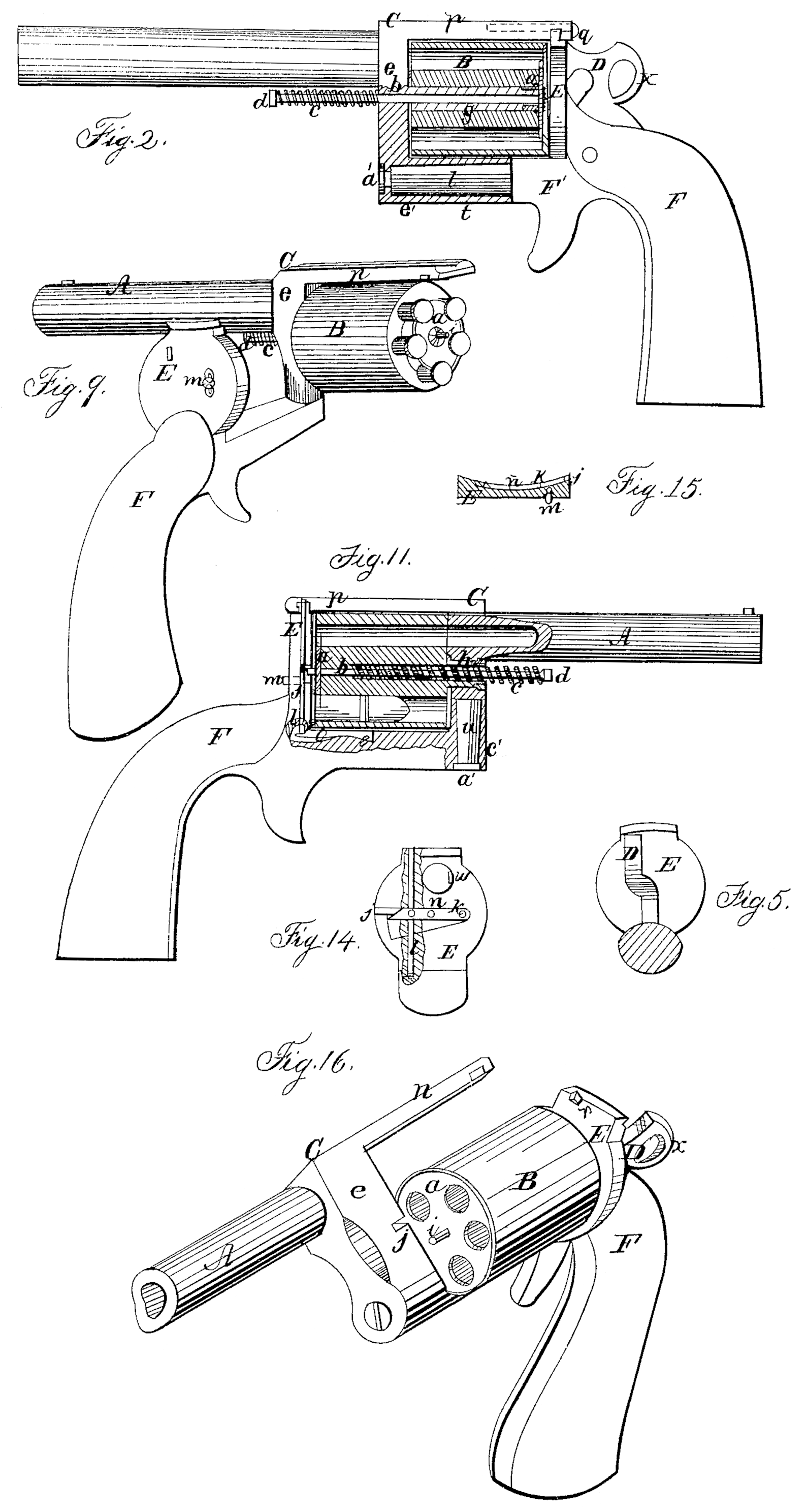
When it is desired to have the cylinder and barrel swing over in a vertical plane, I construct the poste of frame C in the style shown in Fig. 2, in which the part e’ is made to project backward underneath the cylinder at a right angle to e. This part e’ is then bored out longitudinally, thereby forming a sleeve, as clearly shown in section in Fig. 2. The front portion of F’ is then formed into a journal to fit into said sleeve, where it is secured by the screw a’. The upper portion of frame C is so constructed as to extend back from the upper end of poste above the cylinder, forming the bridge-piece p, which reaches back to the recoil or breech plate, with which it engages by a dovetail or lock joint, as shown in Figs. 2, 9, 11, and 16. By these means I secure great accuracy of movement in the parts without having any projection of the joint in front of poste, and at the same time the bridge piece p, by being locked to the breech, receives more or less of the strain caused by the explosion of the charge, and thereby saves the joint below from injury or undue strain, which would otherwise soon render the joint loose, and there by destroy the accuracy of movement necessary to make the arm operate as intended.
When it is desired to have the cylinder and barrel swing round in a horizontal plane the front part of F’ is made to extend upward above the main or horizontal part thereof and at a right. angle thereto, as shown in section in Fig. 11 at c’. This part c is then bored through vertically, thus forming a sleeve, into which the lower portion of part e is fitted, the journal u being formed thereon for that purpose, and the parts being secured together by the screw a’, as in the case above described.
When it is desired to use a cylinder in which the cartridges are inserted and ejected at the front end thereof the frame is constructed as shown in Fig. 2, as it is evident that the front end of the cylinder can only be exposed by having the barrel and frame so pivoted as to swing in a vertical plane, the cylinder in such case being attached at its rear end to the recoil-plate or breech portion of the frame, as shown in Fig. 16.
When the style of frame shown in Figs. 2 and 16 is used I place a sliding bolt, q, (shown in dotted lines in Fig. 2.) longitudinally in a suitable seat provided for it in bridge-piece p, said bolt having a projection on its under side, which, as the bolt is forced back by a spring, engages in the recess or notch r in the front face of recoil-plate E. (Shown in Fig. 16.) The face of this projection on bolt q is so beveled that when the frame is swung into position for firing the bolt will yield automatically as it comes in contact with the face of plate E, and thus permit p to swing into place, where it is securely and automatically locked by bolt q, as already described.
When the style of frame shown in Fig. 9 is used the locking-bolt is located vertically in breech piece or plate E, the special arrangement thereof being hereinafter described.
In order to attach the cylinder properly and fit it for the use of my retractor, I hang it upon a tubular bolt, g, as shown in section in Fig. 2. If the cylinder is to be charged at the rear, then bolt g will be rigidly attached at its front end to post e; but if the cylinder is to be charged at its front end, then the bolt g will be secured to the breech piece or plate E. It is obvious that this bolt g may be formed solid with the frame C or breech-piece E, if desired.
In Fig. 11 I have shown another method of hanging the cylinder which will accomplish the same objects, and which I consider but a modified form of that above described. In this case the cylinder is hung and rotates upon a neck or journal, h, projecting from the end of the cylinder, and which, if desired, may be made solid with the cylinder, forming a part thereof. This journal I will have its bearing in front in post e or in rear in plate E, according as the cylinder is intended to be loaded at front or rear end.
In Fig. 11 the cylinder is shown with the central bore for the passage of the retractor-stem b enlarged or chambered most of the way through. This is done for the purpose of seating the spring c therein, whereby room for its expansion and contraction is obtained without having the stem b protrude so far in front as when the spring is applied entirely outside of the cylinder, as in Fig. 2. The spring may be similarly seated when the tubular bolt g is used by similarly chambering its central bore.
It will be observed that whether the cylinder be hung as shown in Fig. 2 or as in Fig. 11 there is no permanent attachment of the cylinder to the frame except at one end. For the purpose of Tendering the cylinder more secure in its position and insuring the coincidence of its chambers with the bore of the barrel, I provide it with a movable support or bearing at the end opposite that which is attached to the frame. This I accomplish by causing the end of stem b to pass through plate a and project outside of a, as shown by i, Figs. 9, 11, and 16. This projection enters a corresponding groove, i, in the plate E, (or other portion of the frame, if the cylinder loads at the front,) where it has a firm bearing. The projection i is securely held in place by means of latch k, which works in a recess in the face of plate E, said latch k having a notch or recess, n, in its upper edge, which engages with i when the latter is forced into its seat at the center of E, as shown in Fig. 14.
Within the plate E is placed a vertical latch or spring-bolt, l, which is connected to latch k by a pin, m, which passes through and works in a vertical slot in the rear wall of E, where it is provided with a suitable thumb-piece. Bolt l and latch k, being thus pivoted together, are both actuated by spring o, which may be applied as shown in Fig. 11. The end of latch k, and also of bolt l, being properly beveled, as shown in Fig. 14, are automatically forced down— the latter by bridge-piece p of frame C and the former by the projecting point i— as the parts are swung into position for firing. When the parts are in position they are securely locked there by the upper end of bolt l engaging in a suitable recess in the under side of p and the point i engaging in the notch n in latch k.
The hammer is located centrally in the stock for the purpose of allowing the use of the simplest form of lock, and the neck or body of it, as it rises above the stock, is then curved or bent to the left for the purpose of allowing more room for the thumb to operate the thumb-piece in, as shown in Fig. 5. This will bring the point act of the hammer in such a position that it will strike vertically along one side of the face or end of the cartridge, as shown in Fig. 14, in which the position of the cartridge is indicated by a red line. By this means the face of the hammer is made to cover a much larger portion of the rim containing the fulminate than when it strikes radially across said rim, as is usual, and thus the probability of igniting the charge is proportionately increased.
The hammer is constructed as shown in Fig. 2, and so located that no portion of it is elevated above bridge-piece p. Instead of the usual projecting hook, the upper rear portion is formed as shown at x, Fig. 2. object of thus forming the hammer is twofold: first, to prevent it from catching in the bolster or pocket when inserted therein and producing accidental discharges; and, secondly, to prevent it from becoming entangled therein when it is desired to withdraw it for use.
By these various means I provide a revolving arm to which the many-faced retractor can be applied and operated without detaching any of the parts.
By pressing the thumb upon m the pivoted frame and cylinder are instantly released, when, by a slight pressure of the barrel against the saddle, leg, or other object, it is swung round, bringing the nut d on the end of the retractor-stein within reach of the thumb, by a slight movement of which all the cartridge-cases are simultaneously and instantly ejected without the aid of any separate device, and all by the use of one hand only.
By these improvements I also avoid the necessity of detaching the cylinder or any other portion of the arm for the purpose either of removing the cartridge-cases or of reloading it, and hence all danger of dropping or losing any of the parts is entirely avoided. This in the case of mounted troops is very important, and if the arm is to be used in the dark, as is oftentimes the case, this feature is rendered still more important.
By this construction and arrangement of the parts I provide a revolving arm which, by the ease and rapidity of its manipulations, can be repeatedly loaded and fired in an action, whereas the arm as usually constructed is seldom emptied of its charges but a single time; and, finally, I provide perfect security against the accidental discharges now so frequent, and also against the danger of the arm being rendered inoperative or unavailable at a moment when its instant use is of vital importance, as already explained.
Having thus fully described my improvements and their operation, what I claim as of my invention, and desire to secure by Letters Patent, is-
1. The sliding lock-bolt q, arranged in bridge-piece p, as shown and described, whereby the parts can be locked automatically and can be unlocked and swung over by a single application of the thumb, and the whole operation performed by the use of one hand only.
2. Hanging the cylinder on the tubular bolt g or hollow journal h when connected to the frame at one end only, whether at front or rear.
3. Supporting the detached end of the cylinder by the projection i and groove j, substantially as specified.
4. Locking the projection i in place by the latch k, or its equivalent, substantially as shown and described.
5. So arranging bolt l and latch k that both can be operated simultaneously and by a single movement.
6. Constructing and arranging bolt l and latch k in such a manner as to permit the front and rear portions of the frame to be locked automatically as they are swung into position for firing, whereby the use of one hand only is required in the operation.
WILLIAM C. DODGE.
Witnesses:
R. D. O. Smith,
Jno. D. Patten.