
US 24942
UNITED STATES PATENT OFFICE.
S. C. LEWIS AND F. P. PFLEGHAR, OF WHITNEYVILLE, CONNECTICUT.
IMPROVEMENT IN REVOLVING FIRE-ARMS.
Specification forming part of Letters Patent No. 24,942, dated August 2, 1859.
To all whom it may concern:
Be it known that we, S. C. Lewis and F. P. Pfleghar, of Whitneyville, in the county of New Haven and State of Connecticut, have invented certain new and useful Improvements in that Kind of Fire-Arms known as Revolvers; and we do hereby declare that the following is a full, clear, and exact description of the same, reference being had to the accompanying drawings, making part of this specification, in which—
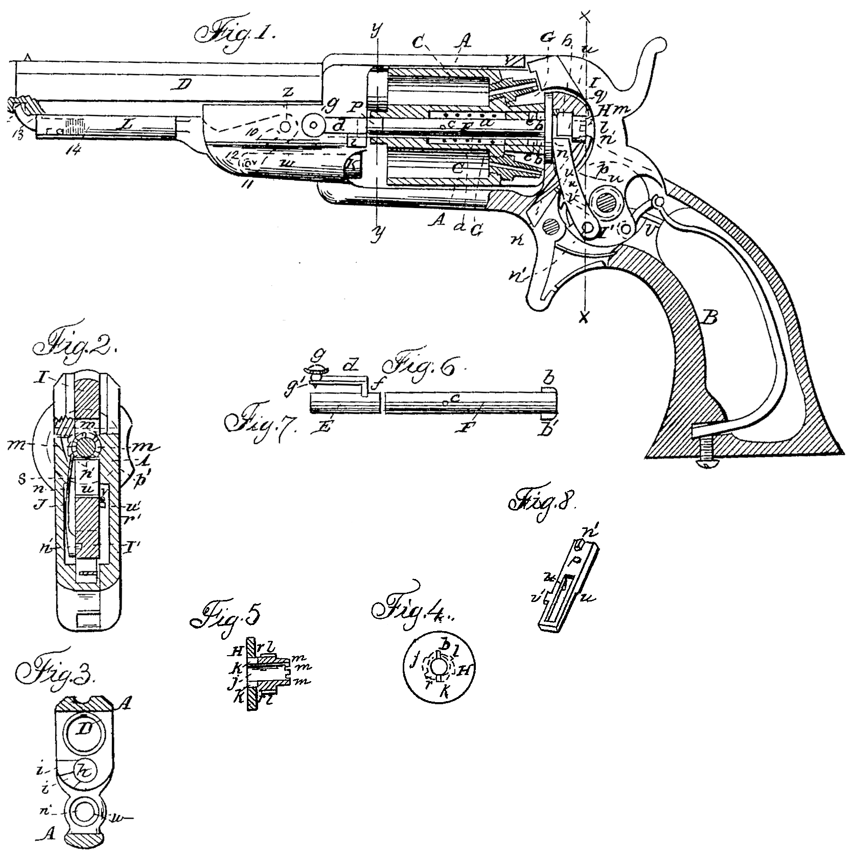
Figure 1 is a longitudinal view, mostly in section, of a pistol with our improvements, Fig. 2 is a transverse section of the same, in the line x x of Fig. 1. Fig. 3 is a transverse section of the same, in the line y y of Fig.1. Fig. 4 is a front view of the rotating recoil-shield. Fig. 5 is a central section of the same. Figs. 6 and 7 are longitudinal views of the two parts of the central pin on which the rotating many-chambered cylinder turns. Fig. 8 is a perspective view of the stop which locks the cylinder at the time of the discharge of its chambers.
Similar letters of reference indicate corresponding parts in all the figures.
Our invention consists in a certain improved construction of and mode of applying the central pin upon which the many-chambered cylinder rotates, whereby greater facility is afforded for the removal of the cylinder when desired.
It also consists in an improved mode of applying the dog and ratchet through which the cylinder derives its rotary motion from the hammer.
It also consists in an improved mode of applying and operating the stop by which the cylinder is locked while the hammer is cocked and during the discharges of its chambers.
It also consists in an improved construction of the recoil-shield.
To enable others skilled in the art to make and use our invention, we will proceed to describe its construction and operation.
AB is the frame, which receives within it the rotating many-chambered cylinder C, and has secured to it the barrel D, and which constitutes the principal portion of the stock. The cylinder C, which has the common arrangement of chambers and vents, is bored right through centrally for the center-pin E F, and is counterbored some distance from the rear to receive a spiral spring, a, Fig. 1, which surrounds a portion of the center-pin. A bush, G is fitted into the rear portion of the counter-bore to fit the center-pin and confine the spring a, and the rear portion of this bush has slots e e on opposite sides of the center-pin to receive two fins, b b, at the rear extremity of the said center-pin E F. The center-pin E F is made in two pieces placed in line with each other.
The back piece,F, which is permanently connected with the cylinder, is of a length equal to or not greater than the length of the cylinder; but the front one, E, may be much shorter. The said piece Fis for the most part cylindrical; but besides having the fins b b upon it, it has a pin, c, inserted through it for the spring a to act upon to press it forward in the cylinder; but the lengths of the fins bb and slots e e are such that when the spring pushes the piece F so far forward that the fins are stopped by coming in contact with the ends of the slots, the said piece projects neither from the front nor the rear of the cylinder, and this is the condition of the said piece F when the cylinder is out of the frame, or when it is not subject to the pressure of the piece E.
The piece E is cylindrical and of a size to fit the central bore of the cylinder. It is fitted into a cylindrical cavity, h, Fig. 3, prepared for it in the front of the part A of the frame, said cavity h being deep enough to receive the whole of said piece. To one side of said piece there is attached an elbow, d f, the portion d of which is elastic and has a knob, g, at its extremity.
At one side of the cavity h there is a notch, i, (see Figs. 1 and 3,) in the frame, into which it is necessary to draw the portion f of the elbow d f to allow the whole of the piece E to enter the said cavity h. Before placing the cylinder in the frame the piece E is inserted to its full length in said cavity h, with the portion d of its elbow outside of the frame; and when the cylinder is placed in the frame the piece E is pushed back by taking hold of the knob, g’, and is turned to bring the portion f of the elbow into a shallower notch, i’, (see Fig. 3,) above the notch i, to prevent it moving forward again, and is locked in this position by a pin, g’, on the inner side of the portion d, springing into a notch provided on the exterior of the frame. The sliding back of the piece E, as above specified, drives it some distance into the cylinder, and in so doing it drives back the piece F and causes its rear extremity to enter into a hole, i, Figs. 5 and 6, in the center of the rotating recoil-shield H. This hole j has two slots, k k, on opposite sides, to receive the two fins b b of the piece F for the purpose of compelling the said piece F and the cylinder to rotate along with the recoil-shield. The piece E constitutes a stationary support to the front end of the cylinder.
To remove the cylinder it is only necessary to lay hold of the knob g and first draw the pin g’ out of its notch in the frame, then turn the piece E far enough to bring the elbow opposite the notch i, when the pressure of the spring a forces forward the piece F, which drives forward the piece E clear of the cylinder and leaves the latter free of the recoil-shield, so that it will drop out of the frame.
The recoil-shield H is fitted into a cavity in the back of the frame A, and has formed in the same piece with it the peripheral ratchet l l and the ring of notches m m, the former to be acted upon by the dog n Figs. I and 2, to produce the rotation of the cylinder, and the latter to be acted upon by the stop p, Figs. 1, 2, and 8, to lock the cylinder. The said shield is kept in its place by a pin, q, which passes through the part A of the frame and enters a groove, r, turned in said shield.
The dog n is made of a piece of spring-steel and has a small pin or projection, n’, permanently secured to it at or near its lower end, and said pin enters a hole in the tumbler I’ of the hammer I. The said dog is confined to the ratchet l l by the movable side plate, J, Fig. 2, of the stock, which constitutes a bearing for it, and in which there is a recess, s, Fig. 2, constituting a guide for said dog. By thus applying the dog to act transversely to the movement of the hammer, in combination with a peripheral ratchet, the dog is made to constitute its own spring, and the construction of the lock of the revolver is much simplified, while greater facility is afforded for taking out and replacing the said dog when necessary.
The stop p consists of a slightly curved piece of spring-steel, having near the top of the front side a tooth, p^2, of a width to enter the notches m m in the rear of the recoil-shield, and having in its back side a projection, u. This stop is placed in an inclined position, (shown in Fig. 1) between the front of the tumbler I’ and the back of the part A of the frame, where it is kept in place by its own elasticity, which keeps it always in contact with the frame, the recoil-shield, and the tumbler. The said stop has applied to it a spring, v, which acts upon a projection, v’, on one side of it, and exerts a tendency to move it bodily downward, and which, when the hammer is down, keeps the said stop, with its tooth p’, in any one of the notches m m that is at the time opposite to it, and so locks the recoil-shield and the cylinder securely against any possibility of revolving.
There is on the front of the tumbler I’ a tooth, u’, which, when the stop p is held down in the position above specified, occupies a position just below the projection u on the back of the stop. During the first part of the drawing back of the hammer to cock it, and before the dog n commences to turn the recoil-shield, the tooth u’, by its action on the projection it, moves up the stop far enough to remove the tooth p’ from the notch m. Almost immediately after having accomplished this the tooth u’, by its circular motion, works clear of the projection u and leaves the stop free to be forced down by the spring v, but as by this time the recoil-shield has commenced to be rotated by the action of the dog n the tooth p’ does not drop back into the notch m when the stop descends, but it rests on the metal between it and the next notch till, as the hammer arrives at full-cock and the rotation of the recoil-shield is completed, the next notch m arrives opposite to the tooth, which instantly drops in and locks the recoil-shield and cylinder.
K, Fig. 1, is the ball-rammer, working in a suitable guide, w, Fig. 3, in the front part of the frame, and slotted vertically to receive within it part of a lever, L, which works on a fixed fulcrum, Z. The lever L contains a curved slot, 10, which receives a roller, 11, that is fitted within the slot of the rammer to a pin, 12, that is inserted transversely through the last-named slot. The lever works the rammer by the action of the curved slot 10 on the roller 11. The front end of the lever L is bored out a short distance to receive the stem of a sliding tooth, 13, which has a spiral spring, 14, applied behind it. This tooth locks the lever close under the barrel by entering a fixed bush, 15, which is fitted tightly into a hole drilled into the bottom of the barrel, near the muzzle thereof, the said bush having its interior conical and largest at the back, so as to afford a good hold for the tooth 13. The point of the tooth is beveled in two ways, so that it will slide into and out of the bush 15 with sufficient freedom.
The reason for using the bush is that the making of a hoe largest at the back in the solid metal of the barrel would be a work of some difficulty.
What we claim as our invention, and desire to secure by Letters Patent, is—
1. The center-pin E F, made in two pieces, one of which is fitted to the rotating cylinder and to a rotating recoil-shield with pins b b, and has applied to it within the cylinder a spring, a, and the other of which is fitted to slide and turn in the front part of the frame, and is capable of being locked to the frame,substantially as herein described.
2. The dog n, constructed and applied as described, to constitute its own spring, and operating transversely to the hammer, in combination with a peripherical ratchet, l l, substantially as and for the purpose herein set forth.
3. The stop p, constructed with a tooth, p, in its front, and a projection, u, on its back, and applied and operating in combination with a spring, v, a ring of notches, on in, on the rear of the recoil-shield or cylinder, and a tooth, u’, on the tumbler, substantially as herein described.
4. The recoil-shield constructed with a peripheral ratchet, l l, a ring of notches, m m, a central bore, j, and slots k k, substantially as and for the purpose herein specified.
S. C. LEWIS.
F. P., PFLEGEAR.
Witnesses:
G. C. Robinson,
Wm. Schallhorn.