
Britain 1175
AD. 1855 № 1175.
Fire-arms.
LETTERS PATENT to Samuel Edwin Robbins, of the State of Vermont, of
the United States of America, for the Invention of “Certain New and Useful Improvements in Fire-arms”— Partly a communication from George Leonard, of the said United States.
Sealed the 8rd August 1855, and dated the 21th May 1855.
COMPLETE SPECIFICATION filed by Samuel Edwin Robbins at the Office of the Commissioners of Patents, with his Petition and Declaration, on the 24th May 1853, pursuant to the 9th Section of the Patent Law Amendment Act, 1852.
TO ALL TO WHOM THESE PRESENTS SHALL COME.
BE IT KNOWN that I, Samuel Edwin Robbins, of the State of Vermont, of the United States of America, do hereby declare that I have made an Invention of “Certain New and Useful Improvements in Fire-arms,” (part or parts of such Invention having been communicated to me by George Leonard, of the said United States,) and I do hereby declare that the said Invention is fully described and represented in the following Specification, and the accompanying Drawings, letters, figures, and references thereof:—
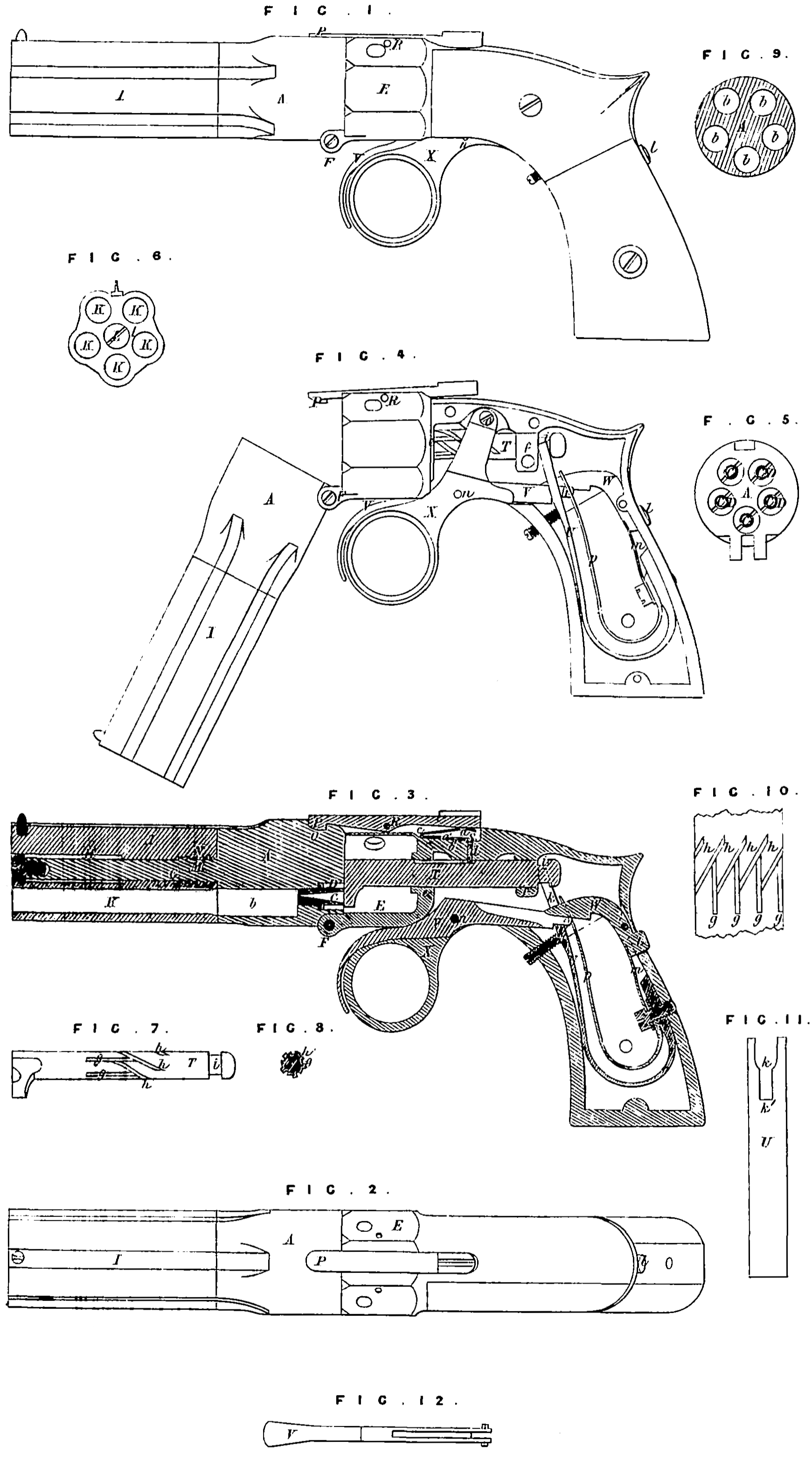
Of these Drawings, Figure 1 exhibits a side view of one of my improved repeating fire-arms; Fig. 2 is a top view of the same; Figure 3 is a central vertical and longitudinal section of it; Figure 4 is a side view of it, showing the lock plate or stock cover as detached, and the moveable chambered cylinder and barrels turned down with respect to the handle or lock, and in order to enable a person to obtain easy access lo the percussion nipples, in order to prime the same, or place caps thereon; Figure 5 is a rear view of the chambered magazine; Figure 6 is an end view of the moveable series of barrels; Figure 7 is a side view of the revolving hammer; Figure 8 is a transverse section of said hammer.
In such Drawings, A denotes a chambered cylinder or magazine, it being pierced with five or any other suitable number of bores or loading chambers b, arranged around, in a circle, as seen in Figure 9, which is a transverse section of such part A. The rear end of each of these loading chambers is provide with a percussion cap or nipple C, such nipple being arranged within a protection chamber D, as seen in the Drawings.
The said magazine A so constructed is hinged to the stock or lock case E, as seen at F, and in such manner as to enable it to be turned down with respect to the stock, as seen in Figure 4, and so as to permit free access to be had to the percussion nipples. From the middle of the chambered magazine A, and in line with its axis, a spindle G projects, and passes through a cylindrical bore or passage H, formed through a moveable block I, in which there is a series of bores or barrels K, K, K, the number of which corresponds to that of the chambers in the magazine.
The front half or part of the bore H is made somewhat larger in diameter than is the rear part of it, the same being in order to enable it to receive the head of the screw L, which is screwed into the extreme outer end of the spindle G. The lower part of the spindle, or that next the magazine, is provided with a male screw M, which is adapted to a corresponding female screw N, made in the lower part of the bore H.
By so combining with the stationary magazine a moveable series of barrels, ready access to the charge chamber may be had at any time for the purpose of supplying the same with charges. In order to accomplish this, it will only be necessary to unscrew the block I from the spindle G, and draw it forwards thereon, the head of the screw L preventing it from separating therefrom. If, now, the pistol be held in a vertical position, the block I being grasped in the left hand; each charge chamber will be brought into a convenient situation to receive its charge of powder and ball. When the block I is screwed closely against the chambered magazine, the axes of the barrels or bores should respectively range in line with those of the charge chambers of the magazine.
The upper part of the chambered cylinder A is provided with a locking recess O, adapted to receive a catch P, which consists of a lever formed and supported upon a fulcrum R, and within a recess c in the stock, as seen in the Drawings. Its rear arm rests upon the upper leaf a of a V spring S, whose lower leaf a’ is supported on a rest b, or upon the bottom of the space or recess c. From the lower leaf of said spring S a stud or pin d extends downward, and enters one of the grooves of a cylindrical shank of a rotary hammer T.
During the reciprocating rectilinear movements of the hammer, theses grooves, acting in conjunction with the spring stud, servo to rotate the hammer in a direction transverse to its axis. The shank of the hammer so supported slides and turns freely in bearings at e, f. It has arranged longitudinally on its surface and at equal distances apart a series of straight grooves (g), corresponding in number with that of the loading chambers of the magazine. Each of these grooves terminates at its rear end in a helical groove A, which makes an acute angle with it, and extends above and below it, and enters the groove next above it, as seen in Figure 10, which is a developement of the grooves upon a plane surface.
Where each helical groove enters a straight groove, its depth is not so great as is the straight groove at the place of intersection. The rear end of each straight groove is also made of a depth less than that part of the helical groove into which it leads.
This arrangement of grooves will cause the hammer to make ao partial revolution whenever it is retracted, the spring-stud passing through a helical groove and dropping into a straight groove, through which, while the hammer is moved forward, the stud also passes, and is received into the helical groove at the rear end of such straight groove; one groove being deeper than its entering groove where they join, prevents the stud from entering into the latter while it is passing by it. The rotary hammer operates successively on the percussion priming or caps, they being stationary relatively to it while the fire-arm is being discharged. This rotary hammer is an important feature of my Invention.
The upper end of the main spring U of the hammer rests in a groove¢ made around and in the latter. The said main spring is provided with a shoulder k, as seen in Figure 11 [which denotes a front view of the spring], such shoulder also being exhibited in Figure 3. Tt operates in connection with the trigger V and with a locking catch W, which is furnished with a secondary trigger or thumb bearer I and a spring m, applied and arranged as seen in Figure 3, said thumb bearer being extended through the lock case or stock, so as to be in a convenient position to receive pressure from the thumb while the stock is held in the hand. The fulcrum n of the trigger is within. a retracting lever X, which turns upon a fulcrum or pin o, and during the act of cucking, the hammer is pulled backward by the middle finger of the hand while it is grasping the pistol by its stock. While moving rearward such lever X forces the shoulder of the trigger against the shoulder k of the main spring, and moves said main spring back until it is seized by a locking catch W, the hammer being in the mean time retracted by the main spring The trigger serves to liberate the catch W from the main spring, such liberation when the trigger is pulled being accomplished by the upward pressure of the rear arm of the trigger against the catch W, the trigger being suitably formed for such purpose, or as exhibited in top view in Figure 12. After each discharge, the forward motion of the trigger and retracting lever is effected by the pressure of a spring p; whenever it may be desirable to let down the hammer without discharging the pistol or fire-arm, it can be accomplished by pressing with the thumb upon the head or bearer of the secondary or thumb trigger J, and casing the hammer down with the finger in the ring of the cocking lever.
I do not claim a single stationary barrel and a rotary chambered magazine, arranged and applied to the stationary barrel, so that each chamber may be moved around so as to be brought into line with the bore of the barrel; but what I do claim is, the combination of & stationary chambered magazine, or series of barrels with a moveable series of bores or barrels, and mechanism by which the latter may not only be connected to the former, so as to bring the axis of its bores respectively in range of these of the magazine, but so practically disconnected, as occasion may require, as to enable the charge chambers of said magazine to be loaded, as specified.
And1also claim the peculiar manner of connecting the chambered magazine and its moveable series of barrels, viz., by means of a spindle G, screw L, or its equivalent, the male and female screws, and a bore H, formed as above specified, the same being applied and made to operate together, substantially as herein before explained
I also claim combining the chambered magazine to the stock by such mechanical devices as will enable the said magazine not only to be turned down into an inclined position with respect to the stock, in manner and for the purpose us described, but to be turned up and locked to the stock, so as to be in a position for its nipples, or the priming thereof, to be acted upon by the revolving hammer.
I also claim the improvement of so applying the hammer to the series of barrels, or the loading chambers, that such hammer, while they are stationary, may be moved around so as to strike on their primings or nipples successively, is specified.
I also claim the application of the main trigger directly to the retracting lever of the main spring and hammer so as to be moveable therewith, in manner substantially as specified
I also claim combining a rest or bearer with the spring S, the lever catch over it, and the pin or stud below it, in order that the spring may not only serve to operate the lever catch but the pin, as above described.
I also claim the mechanism for rotating the hammer during its reciprocating rectilinear movements or rearward motions as described; the same consisting of the spring dog or stud, the series of straight grooves and the series of helical grooves formed in the hammer shank, and arranged at angles and in depths with respect to each other, so that the spring dog may operate in them, as specified.
I also claim the combination of the secondary or thumb trigger with the main trigger, its catch and the main spring, the same being arranged so as to be operated by the thumb while the pistol is held in the hand, as specified.
In testimony whereof, I have hereunto set my signature and seal, this Eleventh day of May, in the year of our Lord One thousand eight hundred and fifty-five.
SAMUEL EDWIN ROBBINS (L.S)