
Britain 583
AD. 1852 № 583.
Revolving Fire-arms.
LETTERS PATENT to Richard Archibald Broomar, of the firm of J. C. Robertson and Company, of 166, Fleet Street,in the City of London, Patent Agents, for the Invention of “Improvements in Revolving Fire-arms.”— A communication
Sealed the 23rd April 1853, and dated the 30th October 1852.
PROVISIONAL SPECIFICATION left by the said Richard Archibald Brooman at the Office of the Commissioners of Patents, with his Petition, on the 80th October 1852.
I, Richard Archibald Broomar, of the firm of J. C. Robertson and Company, of 166, Fleet Street, in the City of London, Patent Agents, do hereby declare the nature of the said Invention for “Improvements in Revolving Fire-arms” to be as follows:—
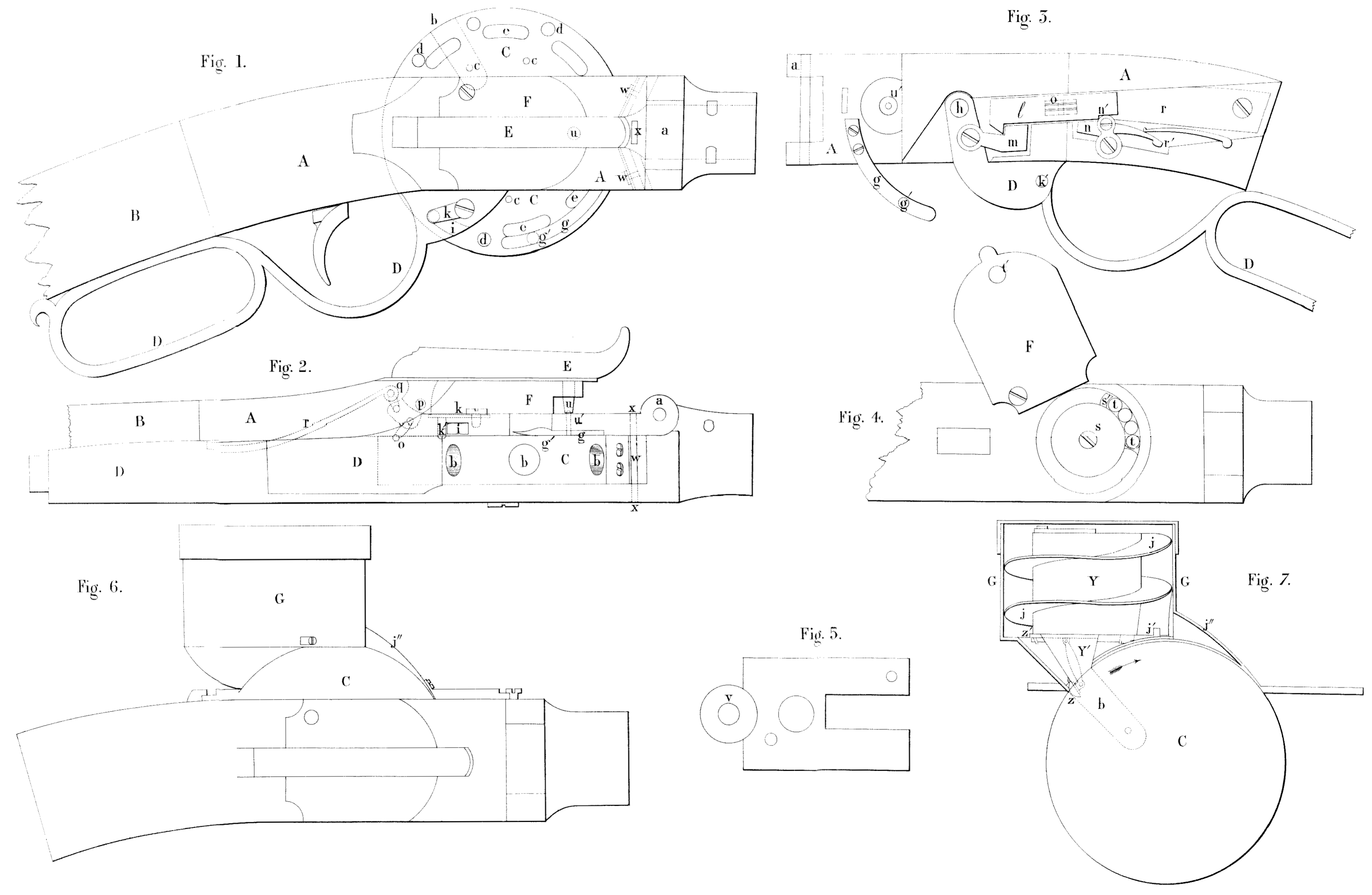
This Invention relates to certain improvements in revolving fire-arms in which Figure L is a side view of the lock, revolving chamber, and part of the breech; Figure II. a view on the under side of the same; Figure III. an interior view of the lock plate, showing the works of the lock; Figures IV. and V. are details; Figure VI. an elevation of the A Jock with the self-loading flask attached; Figure VIL. an interior view of the self-loading flask. That part of the gun containing the lock is divided into two general parts; the first part forms the chamber containing the revolving disk holding the charges,and is permanently fixed to the breech; the other part is the lock plate hinged to the former, and shown at A, the hinge being at (a) near the point where the barrel is attached. The back end of the plate A, fits in the breech and makes a flush joint, and is secured by a cam-headed bolt and lever, which is worked from the outside, so as to attach and detach it with facility. A spring catch or clasp may be substituted for the cam bolt and lever. When the lock plate is thrown open on its hinge, as in Figure III, the revolving disk C, is exposed, so that it may be removed from its axis and readily taken out of the gun and another substituted, charged with the loads, if desired. The piece C, is to contain the loads, and is a narrow cylinder, around the circumference of which is a series of holes b; drilled to n certain depth and directed radially towards the centre; these form the chambers to hold the loads. On that side of C, which plays against the lock plate A, is a series of holes and notches intended to effect the stopping, rotating, and firing loads. C, represents the touch holes; these go through near the bottom of the load chambers; a hole to each chamber; d, are the stop holes; and e, the notches for receiving the point of the rotating lever, The manner in which these arc severally operated upon will now be described:— First, as to the stop: This is a curved spring, seen at g, attached to the lock plate. At g¹ is a pin, which, when the lock plate is closed, presses into the holes d, and will thereby hold the disk C, firmly in place. These holes of course arc so spaced that the disk is always stopped when a load chamber b, is exactly in the line of the barrel. Before the disk can be revolved the spring g, must he moved so as to take the pin g¹, out of its hole d. This is accomplished by the movement of a long lever D, shaped and attached to the Jock plate A, as shown in the Figures, the fulcrum pin being at k, Figure IIL, and the movement of this also effects the rotating of the disk and the cooking. In the edge of D, is o narrow inclined slot shown at the dotted lines i, Figures I. and II; by moving the lever D, towards g, the point of g, enters the slot i, and riding up on its inclined edge pushes the spring back, and with it the stop pin g¹, is withdrawn from the hole d, thus allowing the disk to be moved. At this point another fixture comes in play to rotate,the disk. This is a pin affixed to another spring, and attached to the outside of the lever D, at k. The pin passes through a hole in D, and projects through, as shown at k¹, Figure III. The end of the pin drops into one of the notches w, at the moment of disengaging g¹, and restoring the lever D, to its first position draws along with it the disk C, the extent of the arc described being equal to the distance on the face, of the cylinder from the centre of one load chamber to, that of another. The spring g, being also disengaged from the slot 4, presses the pin, g¹, against the side of C, so that it drops into the-proper stop hole, and arrests the disk-at the proper place. The catches E, are holes elongated on one side, so that the bottom. forms an inclined plane terminating at the face of the disk. In pushing the lever D, forward, this causes.the pin k¹, to ride out, and form in fact a pawl and ratchet arrangement. The movement of the lever D,besides performing these operations; also effects the cocking of the piece. In describing this the construction of the lock will be included. The cocking can, however, be effected independently of the movement of the lever D, by lifting ‘the hammer back with the finger, the same as in common guns, and that too without changing the position of the disk C. This is an important feature, for should a cap explode without igniting the charge, as many more caps may be fixed upon the charge as may be requisite, or until the lot in the primer gives out. It also enables the gun to be used as a‘common one by leading at the muzzle and fixing in, the ordinary way. Thus it is provided that a part of the arm may become deranged, and yet leave it useful as an arm of defence. To cock the gun at the time the disk is revolved, the lever D, is carried forward, as before described. This carries with it a sliding bar or tumbler l, which is connected by a hook m, to D, so that the lever D, will operate but in one direction upon l; the motion is continued until the dog n, drops into the notch n¹, on the tumbler. As soon as this is done the piece becomes cocked, the hammer lifted up, and ready for giving the blow for firing. The other connections for accomplishing this are a lever extending from the tumbler l, to the toc of the hammer. This is attached at one end at o, Figure III, and at the other to the hammer, as seen in dotted lines Figure 2. The hammer is at I, and plays upon the pin p, Figure II. A short stirrup q, connects it to the main spring r, as usual. The trigger operates upon the dog n. at r¹, disengaging it from ow, in order to fire in the common manner. The percussion caps, pills, or other primer are contained in a box outside of the lock plate, and immediately under the hammer. As shewn in the Drawing, percussion caps arc used. The box is seen at F, and at Figure IV. the cover is removed, exhibiting the interior; s, is a box containing a spiral spring, the size is such that room is left to arrange the caps seen at t, around the interior. Through both the top and bottom of F, there is a hole t¹, at the place of the cap t, and beneath that again another in the lock plate leading to the touch hole c, in the disk, being a continuation of the touch hole. The print u, on the hammer passes through the priming box F, and taking a cap t, upon it carries it along to the side of the lock plate immediately over the touch hole, striking and exploding upon it, the fire passing through the copper of the cap and orifice u, in the lock plate leading to the touch hole proper in the disk C. In exploding the cap a small hole is made in its top, which is situated over the orifice, and a minute portion of the copper driven in along with the fire; the rest of the shell sticks to the nipple. As the hammer is withdrawn these fragments fall off, another cap is forced in place by the finger s¹, and the operation repeated as before. It remains now to describe some safeguards to the gun. At Figure V. is a plate which fits upon the inside of the lock plate, so that the part v, fits around the hole u¹, against the disk C. The part v, is of steel, and is slightly disking, so that its inner circumference will press hard upon the disk and form a tight fit all round. The object of this is to enclose the touch hole at every fire within this casing, and thus prevent the possibility of the heat communicating to the other touch hole nearest to it. It also keeps the disk clean, and prevents the accumulation of particles of powder, dust, &e. There are also additional safeguards in this respect by the formation of vents to permit the heat to escape at the place of junction between the edge of the disk and the barrel; at this spot some fire must be forced out. To prevent it as far as possible, and to direct the course of such as dues, is the object of the part now to be described. At Figure 1, at the dotted lines w, are shown two springs fastened within a narrow channel, forming angles inclined forward. The lower edges of these springs press upon the circumference of the disk, and form a very close joint; they keep the face very clean, and also prevent the passage of fire. The angular direction of the channels forward also carries the heat away from the lock and charge in the disk. Besides the two vents just described, there are two others in the sides, as seen at x. The loading of the disk, if done while in the gun, is effected by a rammer attached to a lever hinged at one end, and bending over the top of the disk, so as to act upon the chambers in a manner common to many kinds of fire-arms. In Figures 5, and 6, are views of the self-loading magazine. This is exteriorly a cylindrical case G, fitted to an arch, which exactly covers the dish above the gun, being securely fixed in place by screws, &c. In the interior is a flask y, having an opening at the top to receive powder; at the lower end is a spout y¹, having a hinged valve z, at the mouth; at the top of the spout is a second valve z¹, to cut off and let in the powder. The spout is calculated to hold one charge,’and operate in that respect like a common flask. From the valve z, a lever extends up to the upper valve, so that when s, is closed, z¹ opens, and vice versa. This opening and closing is effected by the rotation of the disk thus:— As shown in the. Drawing, the spout is just over a chamber, and a charge of powder has been let in; it is now to be moved on to bring another chamber in place; as the chamber v, moves on, the side strikes against the top of the valve z, and closes it. It is kept so while it rides over the surface of the disk to the next chamber; as z, closes, z¹, is opened by the action of the connecting rod, and thus a charge of powder falls into the spout y¹; as the next chamber comes under, z, drops open, and the powder is discharged into it, and so on. Next, for the balls: At j, is a spiral plane terminating immediately over the next chamber after the one which bas just received the powder. There is a bar across the bottom which passes through from the outside and through the hole j¹; this bar keeps the bullets back in starting until a chamber comes under which has received its charge of powder; it is then withdrawn, and a ball rolls in. The bullets are dropped in at the top upon the inclined plane j, until the space is taken up. At j”, is an arch which terminate upon the circumference of the disk. The lower half of the ball only enters the hole, but as it is carried along by the rotation of the same it is brought into contact with the arch j”, and thus gradually pressed in. and this effects the ramming down.
SPECIFICATION in pursuance of the conditions of the Letters Patent, filed by the said Richard Archibald Brooman in the Great Seal Patent Office on the 30th April 1858.
TO ALL TO WHOM THESE PRESENTS SHALL COME, I, RicHarp ArciiBaLd Brooman, of the firm of J. C. Robertson and Company, of 166, Fleet Street, in the City of London, Patent Agents, send greeting.
WHEREAS Her most Excellent Majesty Queen Victoria, by Her Lotters Patent, bearing date the Thirtieth day of October, in the year of our Lord One thousand eight hundred and fifty-two, in the sixteenth year; of Her reign, did, for Herself, Her heirs and successors, give and grant unto me, the said Richard Archibald Brooman, Her special licence that I, the said Richard Archibald Brooman, my executors, administrators, and assigns, or such others as I, the said Richard Archibald Brooman, my executors, administrators, and assigns, should at any time agree with, and no others, from time to time and at all times thereafter during the term therein expressed, should and lawfully might make, use, exercise, and vend, within the United Kingdom of Great Britain and Ireland, the Channel Islands, and Isle of Man, anInvention for “Improvements in Revolving Fire-arms” communicated to me by a foreigner residing abroad, upon the condition (amongst others) that I, the said Richard Archibald Brooman, by an instrument in writing under my hand and seal, should particularly describe and ascertain the nature of the said Invention, and in what manner the same was to be performed, and cause the same to be filed in the Great Seal Patent Office within six calendar months next and immediately after the date of the said Letters Patent.
NOW ENOW YE, that T, the said Richard Archibald Brooman, do hereby declare the nature of my said Invention, and in what manner the same is to be performed, to be particularly described and ascertained in and by the following statement
This Invention consists of improvements in the construction and arrangement of revolving fire-arms. Figure I. of the Drawings annexed is a side view: of the lock, revolving chamber, and part.of the breech of n revolving fire-arm constructed according to these improvements; Figure 2, a view on the under side of the same; Figure 8, a sectional view of the lock plate, shewing the works of the lock; Figures 4, and 5, shew detached parts; Figure 6, is an elevation of the lock with self-loading flask attached; Figure 7, a view in section of the self-loading flask.. That part of the gun which contains the lock is divided into two parts; the first part forms the chamber containing the revolving disc holding the charges, and is permanently fixed to the breech. The other part is the lock plateA, which is hinged to the former part at (n). near the point where the barrel is attached. The back end of the plate A, fits in the breech and makes a flush joint, and is secured by a cam-headed bolt and lever, which is worked from the outside, so as to allow it to be attached and detached with facility. A spring catch or clasp may be substituted for the cam bolt and lever. When the lock plate is thrown open on its hinge, as in Figure 3, the revolving disc C, is exposed, so that it may be removed from its axis and readily taken out of the gun, and another substituted, charged, if desired. The piece C, is to contain the charges. It is a narrow cylinder, having around the circumference a series of holes (b) drilled to a certain depth, and directed radially towards the centre; these form the chambers to hold the charges. On that side of C, which plays against the lock plate A, is a series of holes and notches, intended to effect the stopping, rotating, and firing. (c) represents the touch holes which go through near the bottom of the charge chambers, a hole to each chamber; (d) are the stop holes, and (e) the notches for receiving the point of the rotating lever. The manner in which these are severally operated upon will now be described:— First, as to the stop: This is a curved spring. seen at (g), attached to the lock plate; (g¹) is a pin, which, when the lock plate is closed, presses into the holes (d), and thereby holds the disc C, firmly in place. These holes are so spaced that the disc is always stopped when a charge chamber (3) is exactly in the line of the barrel, Before the disc can be turned round the spring (g) must be moved so as to take the pin (g¹) out of its hole (d). This is accomplished by the movement of a long lever D, shaped and attached to the lock plate A, as shewn in the Figures, a pin A, serving as fulcrum, Figure 3, and the movement of this also effects the rotating of the disc and the cocking. In the edge of D, is a narrow inclined slot, shown at the dotted lines (i), Figures 1, and 2; by moving the lever D, toward (g) the point of (g) enters the slot (f), and riding up on its inclined edge pushes the spring back, and with it the stop pin (g¹) is withdrawn from the hole (d), thus allowing the disc to be moved. At this point another pin comes in play to cause the disc to rotate. This pin is affixed to another spring, and attached to the outside of the lever D, at (k). The pin passes through a hole in D, and projects through, as shown at (k¹), Figure 8. The end of the pin drops into one of the notches (E) at the moment of disengaging (g¹), and restoring the lever D, to its first: position draws along with it the disc C; the extent of the arc described being equal to the distance on the face of the cylinder from the centre of one charge chamber to that of another. The spring (g) being also disengaged) from the slot (i) presses the pin (g¹) against the side of C, so that it drops into the proper stop hole, and arrests the disc at the proper place. The catches (E) are holes elongated on one side, so that the bottom forms an inclined plane, terminating at the face of the disc. In pushing the lever D, forward, this causes the pin (k¹) to ride out, and form in fact a pawl and ratchet arrangement. The movement of the lever D, besides performing these operations, also effects the cocking of the piece. In describing this the construction of the lock will be included. The cocking can, however, be effected independently of the movement of the lever D, by lifting the hammer back with the finger, as in common guns, and that too without changing the position of the disc C. This is an important feature, for should a cap explode without igniting the charge, as many more caps may he fixed upon the charge as may be requisite, or until the Jot in the primer gives out. It also enables the gun to be used as a common one by loading at the muzzle, and fixing in the ordinary way. Thus if a part of the fire-arm become deranged it yet remains useful as an arm of defence. To cock the gun at the time the disc is made to revolve, the lever D, is brought forward, as before described, and carries with it a sliding bar or tumbler (l), which is connected by a hook (m) to D, so that the lever D, will operate but in one direction upon (I); the motion is continued until the dog (n) drops into the notch (n¹) on the tumbler. As soon as this is done the piece becomes cocked, the hammer lifted up, and ready for giving the blow for firing. The other connections for accomplishing this are a lever extending from the tumbler (l) to the toe of the hammer. This is attached at one end at (o), Figure 3, and at the other to the hammer as seen in dotted lines, Figure 2. E, is the hammer; it plays upon the pin (p), Figure 2. A short stirrup (g) connects it to the main spring (r) as usual. The trigger operates upon the dog (n) at (r¹), disengaging it from (n¹) in order to fire in the common manner. The percussion caps, pills, or other primer arc contained in a box F, outside of the lock plate, and immediately under the hammer. As shown in the Drawing, percussion caps arc used. Figure 4, shews the interior of the box, the covering being removed. (s) is a box containing a spiral spring of such a size that room is left to arrange the caps (t) around the interior. Through both the top and bottom of F, is a hole (t¹) at the place of the cap (t), and beneath. that again another in the lock plate leading to the touch hole (c) in the disc, being a continuation of the touch hole. The point (u) on the hammer passes through the priming box F, and taking a cap (t) upon it carries it along to the side of the lock plate immediately over the touch hole, striking and exploding upon it, the fire passing through the copper of the cap and orifice (u) in the lock plate leading to the touch hole proper in the disc C. In making the cap explode a small hole is made in its top which is situated over the orifice, and a minute portion of the copper driven in along with the fire; the rest of the shell sticks to the nipple. As the hammer is withdrawn these fragments fall off, another cap is forced in place by the finger (s¹), and the operation repeated as before. It remains now to describe some safeguards to the gun. At Figure 5, is o plate which fits upon the inside of the lock plate so that the part (v) fits around the hole (u¹) against the disc C. The part (v) is.of steel, and is slightly dishing, so that its inner circumference will press hard upon the disc, and form a tight fit all round; the object of this is to enclose the touch hole at every fire within this casing, and thus prevent the possibility of the heat communicating to the other touch holes nearest to it. It also keeps the disc clean, and prevents the accumulation of particles of powder, dust, &c. There are also additional safeguards in this respect by the formation of vents to permit the heat to escape at the place of junction between the edge of the disc and the barrel; at this spot some fire must be forced out. To prevent this as far as possible, and to direct the course of such as does, is the object of the part now to be described. The dotted lines (w, w, Figure 1,) are two springs fastened within a narrow channel, forming angles inclined forward. The lower edges of these springs press upon the circumference of the disc, and form a very close joint; they keep the face very clean, and also prevent the passage of fire. The angular direction of the channels forward also carries the hent away from the lock and charge in the disc. Besides the two vents just described, there are two others in the sides, as seen at (x) The loading of the disc, if done while in the gun, is effected by a rammer attached to a lever hinged at ono end, and bending over the op of the disc, so as to act upon the chambers in 2 manner common to many kinds of fire-arms. In Figures 5, and 6, are views of the self loading magazine. This is exteriorly a cylindrical case G, fitted to an arch which exactly covers the dish above the gum, being securely fixed in place by screws, &c. In the interior is a flask (Y), having an opening at the top to receive powder; at the lower end is a spout (Y¹), having a hinged valve z, at the mouth; at the top of the spout is a second valve z¹ to cut off and let in the powder. The spout is calculated to hold one charge, and operate in that respect like a common flask. From the valve (z) a lever extends up to the upper valve, so that when (z) is closed (z¹) opens, and vice versa. This opening and closing is effected by the rotation of the disc thus:— As shown in the Drawing, the spout is just over a chamber, and a charge of powder has been let in; it is now to be moved on to bring another chamber in place; as the chamber (b) moves on, the side strikes against the top of the valve (z), and closes it. It is kept so while it rides over the surface of the disc to the next chamber; as (z) closes (z¹).is opened by the action of the connecting rod, and thus a charge of powder falls into the spout (Y¹); as the next chamber comes under, (z) drops open, and the powder is discharged into it, and so on. Next, for the balls: (j) is a spiral plane terminating immediately over the next chamber after the one which has just received the powder. There is a bar across the bottom which passes through from the outside, and through the hole (j¹); this bar keeps the bullets back in starting until a chamber come under which has received its charge of powder; it is then withdrawn, and a ball rolls in. The bullets are dropped in at the top upon the inclined plane (j) until the space is taken up. At (j¹¹) is an arch which terminates upon the circumference of the disc. The lower half of the bail only enters the hole, but as it is carried along by the rotation of the same it is brought into contact with the arch (j¹¹), and thus gradually pressed in,whereby the ramming down is effected.
And having now described the nature of the said Invention, and the manner in which the same is to be performed, I declare that I claim as of my said Invention,—
First, the arrangement and combination of the disc C, and guard lever D, whereby the cocking is effected without moving the disc, or unlocking it from its stop.
Second, the combination of the hammer with the lock and guard lever D, in such way as to permit the cocking and firing repeatedly upon one chamber of the disc C, independently of any action upon the other parts connected with the said guard lever, as herein-before described.
Third, the springs (w) (or their equivalent) for keeping as a close a joint between the disc C, and the barrel as possible, so as to prevent the communication of heat to the charges in the other chambers at the time of firing.
Fourth, the giving such an angle to the vents as to project the escaping heat at the joints before described in a direction away from the disc and load.
Fifth, the sliding tumbler (l) combined with the guard lever and lock in such a way that side guard lever only acts upon it in one direction.
Sixth, the touch-hole guard (v) in combination with the disc for confining the heat from the explosion, as described.
Seventh, the several vents described for giving passage to the escaping heat about the joints formed between the disc and barrel.
Eighth, the self-loading apparatus, constructed and operating as represented in Figures 6, and 7, and herein-before described.
In witness whereof, I, the said Richard Archibald Broomam, have hereunto set my hand and seal, this Thirtieth day of April, One thousand eight hundred and fifty-three.
R. A. BROOMAN. (L. S.)