
Britain 14027
AD.1852 № 14,027.
Fire-arms, and Projectiles, &c., to be used therewith.
RICHARDS’ SPECIFICATION.
TO ALL TO WHOM THESE PRESENTS SHALL COME, I,
William Westley Richards; of Birmingham, in the County of Warwick, Gun Manufacturer, send greeting.
WHEREAS Her present most Excellent Majesty Queen Victoria, by Her Royal Letters Patent, under the Great Seal of the United Kingdom of Great Britain and Ireland, bearing date at Westminster, the Twentieth day of March, One thousand eight hundred and fifty-two, in the fifteenth year of Her reign, aid, for Herself, Her heirs and successors, give and grant unto me, the said William Westley Richards, my exors, admors, and assigns, Her especial licence, full power, sole privilege and authority, that I, the said William Westley Richards, my exors, admors, and assigns, or such others, as I, the said William Westley Richards, my exors, admors, or assigns, should at any time agree with, and no others, from time to time and at all times during the term of years therein expressed, should and lawfully might make, use, exercise, and vend, within England, Wales, and the Town of Berwick upon Tweed, my Invention of “Certain Improvement in Fire-arms, and in the Means used for Discharging the same, also Improvements in Projectiles;” in which said Letters Patent is contained a proviso that I, the said William Westley Richards, shall cause a particular description of the nature of my said Invention, and in what manner the same is to be performed, by an instrument in writing under my hand and seal, to be inrolled in Her said Majesty’s High Court of Chancery within six calendar months next and immediately after the date of the said in part recited Letters Patent, as in and by the same, reference being thereunto had, will more fully and at large appear.
NOW KNOW YE, that in compliance with the said proviso, I, the said William Westley Richards, do hereby declare that the nature of my said Invention, and the manner in which the same is to be performed, are fully described and ascertained in and by the following statement thereof, reference being had to the Drawings hereunto annexed, and to the figures and letters marked thereon, that is to say:
My Invention consists,— Firstly, of improvements in the construction of revolving pistols.
Secondly, of an improvement in the construction of the muzzles of rifles.
Thirdly, of an improved swivel for gun locks.
Fourthly, of improvements in percussion caps and primers for discharging fire-arms
Fifthly, of an improved projectile, and an improved material for making waddings.
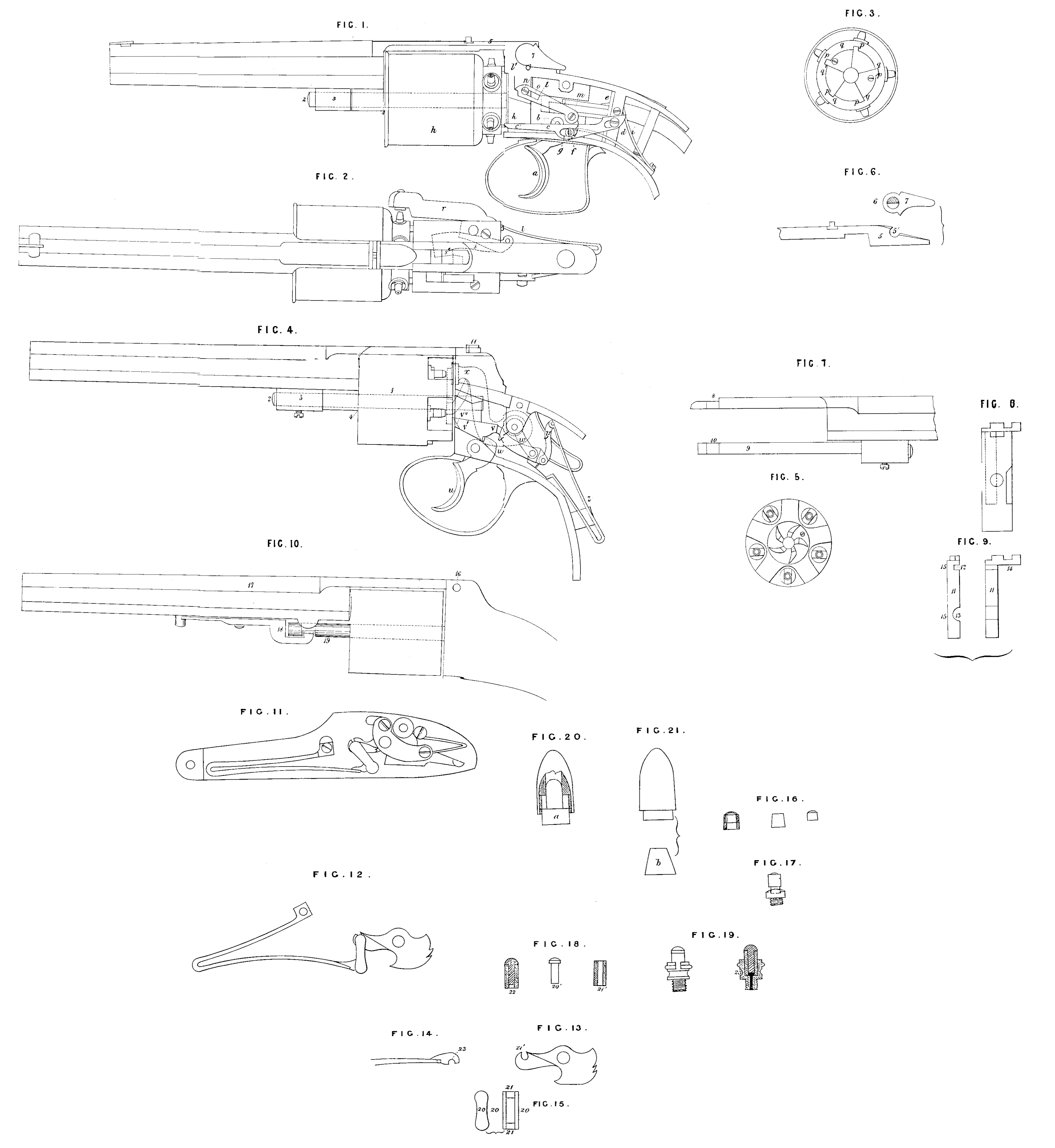
Figure 1, represents a side elevation of a revolving pistol con structed according to my Invention; and Figure 2, represents the same in plan; the stock and side plates of the said pistol being removed in both Figures, so as to expose the interior of the lock to view. a, is the trigger turning upon the joint b; c, is a lever turning upon the pin d, but capable also of a horizontal motion upon the said pin equal to the length of the slot e; a pin f; on the trigger a, enters the slot g, and by pulling the said trigger in the act of dis charging the pistol the end c¹ of the lever c is raised vertically, and being pressed against the end of the barrel h, by the spring i, causes the partial rotation of the barrel by engaging under the tooth k, of the said barrel. On loosing the trigger the lever c is brought back to the position represented in the Drawing, the end of the said lever sliding over the inclined face of that tooth on the barrel under which it next engages itself. l, is a slide which is jointed to the trigger at m, and the motion of which is directed by the pin n, in the framing of the lock, passing through the slot o, in the said slide. When the trigger is pulled, the slide moves simultaneously with the lever c, and its end advancing to the end of the barrel h, the point l bears against the upper surface of the tooth under which the lever c is engaged, so that during the discharge of the pistol the barrel is held firmly by one of its teeth being held between the ends of the lever c and slide l. Figure 3, represents the barrel h, in end view, and shews the teeth on the same. The slide l, Fig. 1, bears against the edges marked p, in Fig. 8; and the lever c, against the edges marked q. The hammer r, see Fig. 2, is placed on the side of the pistol, and has a horizontal motion. The end of the trigger engages against the end of the swivel s, jointed to the hammer e; and on the motion of the trigger a, the swivel s, is pressed forward, and the hammer r, raised by the continued motion of the trigger, the end of the said trigger escapes from the end s’ of the swivel s, and the hammer r, being now disengaged, it falls by the operation of the spring t, and discharges the pistol.
Figure 4, represents in side elevation another of my improvements in the construction of the locks of revolving pistols. u, is the trigger, the end u’ of which engages against the shoulder v’ on the lever v. This lever is jointed to the arm w, on the axis of the hammer x, (shewn in dotted lines), and also to the link or swivel y, which connects it with the main spring z. The end of the barrel is furnished with teeth, as shewn in the end view of the said barrel, Figure 5. The action of the several parts of the lock, Figure 4, is as follows:— When the trigger u is pulled in the act of discharging the pistol, the lever v is by the motion of the trigger moved horizontally, and the end v!! raised vertically by its horizontal motion, the said end has been engaged under one of the teeth of the barrel 1, and by its vertical motion it has raised the said tooth vertically, and thus effected a partial rotation of the said barrel. During the motion of the lever v, just described, the arm w, has been brought into a vertical position, and consequently the hammer on the other end of the same axis has been raised; as the trigger approaches the limit of its motion the end u’ escapes from the hook or shoulder v’, and all the parts (excepting the trigger u) are brought very nearly into the position represented in the Drawing by the action of the main spring z. The inclined face of the lever v rests upon the curved end of the trigger, and is pressed thereon by the main spring, but as the curvature of the said end of the trigger is excentric to the axis of the said trigger, the pressure of the lever v thereon tends to bring the trigger into the position represented in the Drawing. When the finger is removed from the said trigger it moves as described, and again engages itself with the shoulder v’ of the lever, the whole of the parts again assuming the positions represented.
Another of my improvements in the construction of revolving pistols consists in the method of connecting the revolving barrels of the said pistols with the other parts of the same. This part of my Invention is illustrated in Figures 1 and 4, and consists in placing the journal or collar 3, in which the axis 2 of the barrels h and 1 work at such a distance from the said barrels as that the gaseous matter arising from the explosion of the powder, and a portion of which escapes at 4, shall not corrode the said axis and its collar or journal. By this method of construction the fixing of the barrel, which sometimes occurs in revolving pistols of the ordinary construction, is avoided.
One of my improved methods of attaching and detaching the single barrel of revolving pistols to and from the body of the said pistol is represented in Figures 1 and 6. The break-off 5 of the barrel is made of the shape represented in Figure 6. 6, is an axis connected with the arm or lever 7, and working on the top of the body of the pistol. This axis is semi-cylindrical, as seen in the section, Figure 6; and when the said axis is in the position represented at 6, the break-off 5 can pass under the same; but on turning the lever 7 so as to make the axis 6 make a half revolution the semi-cylindrical part shewn in section enters the semi-cylindrical v ity 5′ in the break-off, and prevents the said break-off from being withdrawn from under the said axis. By causing the axis to make a further half revolution the break-off becomes again detached. I sometimes modify that part of my Invention last described in the manner illustrated in Figures 4, 7, 8, and 9. In this modification the axis of the revolving barrel is attached to the single barrel, and the break-off of the single barrel has a semi-cylindrical depression cut on its side, as shewn at 8, in Fig. 7; and the axis 9, Fig. 7, has a similar cylindrical depression cut on its side, as shewn at 10. When the barrel is put in its place, as shewn in Figure 4, the axis 11, shewn separately in Fig. 9, is turned in such a position that the end of the break-off passes by the part 12 of the axis, and the end of the axis of the barrel 9 passes by the part 13 of the said axis, Figure 9. When the break-off has been put in its proper place, the axis, Figure 9, is turned by the arm 14, and the cylindrical part 15 of the said axis entering the semi-cylindrical depressions 8, 10, on the break-off and axis 9, the barrel becomes fixed in its place. See also Figure 8, which represents a front view of the body of the pistol; the revolving and single barrel being removed.
Figure 10, represents another of my improved methods of connecting and disconnecting the single barrel of revolving pistols to and from the stock and revolving barrel of the same. In this pistol the axis of the revolving barrel is connected with the body of the pistol; the break-off or hook is made to hook under the axis 16, by raising the single barrel 17 into a nearly vertical position. When the said single barrel is brought into the position represented in the Drawing the catch or lever 18 is turned so as to engage it in the axis 19 of the revolving barrel, and the single barrel is thereby secured in its place.
Figures 11, 12, 13, 14, and 15, illustrate my improved swivel for gun locks. Figure 11, represents in elevation the interior of a gun lock in which the swivel is constructed according to my Invention. Figure 12, represents the swivel connected with the spring and tumbler. Figures 13, and 14, represent the tumbler and end of the spring, and illustrate the manner in which the swivel is attached thereto. Figure 15, represents a side and a front view of the swivel. The swivel consists of the two links 20, 20, connected at top and bottom by the axes 21, 21, the whole being welded together so as to constitute one piece. The hooked end of the main spring is made very strong, as shewn in Figure 14. The manner in which the swivel hooks on the crane 22 of the tumbler, and the end 23 of the spring, is so clearly shewn by the several Figures 12, 13, 14, that I do not deem further description necessary. After the swivel has been hooked on the crane 22 of the tumbler I sometimes connect it therewith, so to render it inseperable from the said tumbler, by extending the point 22′, of the said crane over the axis of the swivel, so as to prevent the said axis from rising out of its bearing; but I sometimes also leave the swivel moveable from its bearing. A swivel constructed according to my Invention is much stronger than an ordinary swivel, and is not so liable to break.
My improvement in the muzzles of rifle barrels consists in making or lining the said muzzles with steel. In carrying this part of my Invention into effect I prefer to line the said muzzle to the distance of about an inch with steel, or make the said muzzle altogether of steel by welding a piece of steel to the end of the barrel. In lining the muzzle with steel I take care to have a thickness of steel greater than the depth of the rifle to be cut on the barrel. After the barrel has been rifled I harden the steel or lined muzzle in the usual manner. By my improved method of constructing the muzzles of rifles the wearing and enlargement of the bore by the use of iron ramrods, by the friction of the ball in discharging, as well as in the process of cleaning, is effectually prevented. Figures 16, and 17, represent my improved percussion cap. It consists of a tube of gutta percha, in the upper part of which a percussion cap of the ordinary form and construction is inserted, as shewn in the section, Figure 16. In putting my improved cap on the nipple of the gun (see Figure 17) the lower part of the gutta percha tube in which the common cap is fixed fits the said nipple so tightly that access of water to the said cap is prevented. Although I prefer to make the tube of gutta percha, yet I do not confine myself to its use, as other flexible and elastic substances may be substituted for gutta percha.
Figure 18, represents my improved primer, and Figure 19, represents the same applied to a suitable touch-hole. The said primer consists of a tube of gutta percha or other elastic or flexible material of about half an inch long, and having an external diameter of a quarter of an inch, and an internal diameter of about one eighth of an inch. I prefer these proportions, but do not confine myself thereto. A steel or iron peg, having the shape represented at 20′, Figure 18, is inserted in the said tube, and fits it tightly. N The peg 20′ being somewhat shorter than the tube 21′; there is 1eft at the bottom of the said tube a vacant space 22, which is filled with detonating composition. I insert in the gun with which my improved primer is used a touch-hole of the form represented in Figure 19, and which consists of a small chamber screwed into the breech of the gun, and communicating therewith. When the primer is put in its place in the chamber 23, about one half of the said primer projects above the said chamber, and resembles in form and size the ordinary nipple. My improved primer requires no alteration in the ordinary percussion gun, excepting the removal of the cone on which the percussion cap is placed, and the substitution of the touch-hole, Figure 19. After the discharge of the gun the primer is easily removed by the thumb and finger, and a fresh one substituted. My improved primer is very secure against damp.
Figures 20, and 21, illustrate one of my improvements in projectiles. The said improvement resembles the projectiles commonly known as the Minié ball rifle, excepting in respect of the form and material of the part called the core, that is to say the part against which the projecting force first acts,and which is forced into and expands the Lo projectile. In making the said core according to myInvention, I make it of horn, gutta percha, wood, or such other substances (being non metallic) as may be readily moulded or formed into the desired form, and which combine with sufficient hardness such a degree of plasticity as will occasion the said core on the explosion of the powder to enter and expand the projectile. I prefer making the said cores of the forms represented by a in Figure 20, and b, Figure 21; but I do not confine myself to any particular shape; as my Invention consists in the material of which the said cores are made, and not in the shape of the same
Another of my improvements in projectiles consists in the insertion of a ring, made of tin plate or other hard metal, in the interior of hollow rifle balls, such as are represented in Figures 20, and 21; the said rings may be of about half an inch in depth; they serve to strengthen the edge of the projectile, and prevent injury to it, in case of falling or being struck on the edge.
My improvement in wadding consists in making the said wadding of a mixture of gutta percha and rasped cork. I mix the said gutta percha and cork raspings by fusing the former, and then stirring the latter therein, or I mix them in any other convenient manner; I after wards spread or roll the said mixture into sheets of the required thickness by any of the methods used for spreading or rolling gutta percha and cut the waddings of any desired size by punches in the usual manner.
Having now described the nature of my said Invention, and in what manner the same is to be performed, I wish it to be understood that I do not limit myself to the precise methods of carrying my Invention into effect herein described, and represented in the a¢companying Drawings, as the same may be varied without departing from the nature of my said Invention; but I claim;—
Firstly, the method herein described, and represented in the Figures 1,2, and 3 of the accompanying Drawing, of constructing a revolving pistol, that is to say of giving the hammer a horizontal motion.
Secondly, the method of constructing the lock of a revolving pistol herein described, and represented in Figures 4 and 5 of the accompanying Drawing, that is to say, in which the whole action of the said lock is effected by the use of one spring.
Thirdly the methods herein.described and represented in Figures 1, 2, 4, 6, 7, 8, 9, and 10 of the accompanying Drawings, of connecting the single barrel of revolving pistols with the body and revolving barrel of the same, and the application of the same to rifles and guns.
Fourthly, the method herein described, and illustrated by Figures 11, 12, 13, 14, and 15 of the accompanying Drawings, of constructing the swivels of gun locks.
Fifthly, the method herein described of constructing the muzzles of rifles wholly or partially of steel.
Sixthly, the methods herein described, and illustrated by Figures 16, 17, 18, and 19 of the accompanying Drawings, of constructing percussion caps and primers for discharging fire-arms.
Seventhly, the use of gutta percha, horn, wood, and other yielding materials (being non-metallic) for the construction of the cores of hollow conical projectiles, and the insertion of hard metal rings in hollow projectiles.
Eighthly, the use of a mixture of gutta percha and cork in raspings or coarse powder for the construction of waddings.
In witness whereof, I, the said William Westley Richards, have hereunto set my hand and seal, this Seventeenth day of September, in the year of our Lord One thousand eight hundred and fifty-two.
WILLM. WESTLEY. (L.S.) RICHARDS.
AND BE IT REMEMBERED, that on the Seventeenth day of September, in the year of our Lord 1852, the aforesaid William Westley Richards came before our said Lady the Queen in Her Chancery, and acknowledged the Specification aforesaid, and all and every thing therein contained and specified, in form above written. And also the Specification aforesaid was stamped according to the tenor of the statute made for that purpose.
Enrolled the Twentieth day of September,in the year of our Lord One thousand eight hundred and fifty-two.