
US 53881
UNITED STATES PATENT OFFICE.
SYLVESTER. H. ROPER, OF ROXBURY, MASSACHUSETTS,
IMPROVEMENT IN REVOLVING FIRE-ARMS.
Specification forming part of Letters Patent No. 53,881, dated April 10, 1866.
To all whom it may concern:
Be it known that I, Sylvester H. Roper, of Roxbury, county of Norfolk, and State of Massachusetts, have invented certain new and useful Improvements in Breech-Loading and Repeating Fire-Arms; and I do hereby declare that the following is a full and exact description thereof, reference being had to the accompanying drawings, and to the letters of reference marked thereon.
The fire-arm to which my invention relates is adapted to the use of the well-known metallic flanged cartridge primed with percussion fulminate at its base.
The nature of my invention consists in the combination of a revolving cartridge carrier or magazine, located at the rear end of the barrel, with a piston, which at each stroke of the hammer pushes forward a cartridge into the barrel, and there explodes it, the said piston at the same time serving as a breech-plug to close the rear end of the barrel and receive the recoil; and in appropriate mechanism to carry this leading feature of my invention into effect.
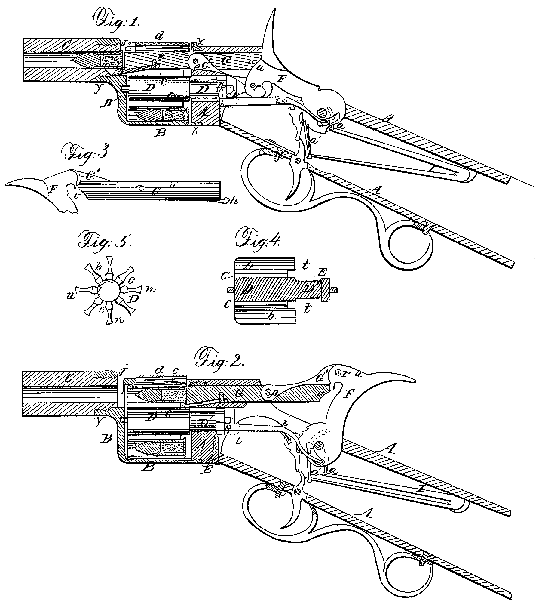
In the accompanying drawings, Figure 1 is a vertical longitudinal section of that portion of the gun which contains the lock, the revolving carrier, and the rear end of the barrel, the hammer being down, as when the gun is discharged. Fig. 2 is a similar section, showing the hammer drawn back to a full cock. Fig. 3 is a view of the piston or breech-plug, the head of the hammer, and the link which connects them. Fig. 4 is a vertical longitudinal section of the revolving carrier, and Fig. 5 is a rear-end View of the same.
A is the breech-piece or frame which carries the lock, the front end being cylindrical, and forming the rear end of the cylindrical chamber which contains the revolving carrier. B is a cylindrical case, within which the carrier revolves, and which is screwed to the front cylindrical end of the breech-piece at x. C is a section of the barrel, screwed to the cylindrical case at y. D is the revolving carrier, with the rear end of its axis D’ extending through the front cylindrical end of the breech-piece A, and having a ratchet-wheel, E, on its rear end. The rear journal, on which this ratchet-wheel, with the revolving carrier, turns, has its bearing in a plug or stud at the rear end of the bore, in which the axis D’ and the ratchet-wheel E are inserted, covering said bore in the rear.
F is the hammer; G, the piston or breech-plug, and G’ a link connecting the piston with the head of the hammer. His a double-acting spring, the front end of which, moving in a narrow slot formed by cutting away the side of the plug or stud immediately in the rear of the ratchet-wheel, acts upon said ratchet to move the revolving carrier one-eighth of a revolution whenever the hammer is drawn back to a full-cock, as will be hereinafter more fully explained. I is the mainspring, which actuates the hammer. Each end of this spring is connected with the foot of the hammer by means of a separate stirrup, a and a’, and these stirrups are so connected with the foot of the hammer that their connecting-points are at right angles to each other in respect to the center-pin, on which the hammer turns. The forward stirrup, a’, is attached to the foot of the hammer at a greater distance from the center-pin than the rear one, and so attached and arranged that the spring acts upon the greatest leverage as the hammer is just finishing its stroke, so that the hammer moves with an increasing velocity from the beginning to the end of its stroke. These two stirrups, connecting, each end of the mainspring with the hammer, as aforesaid, tend to lessen the friction on the center-pin.
The revolving carrier is somewhat similar in form and construction to the revolving cylinder in an ordinary revolving fire-arm, except that instead of being bored with a series of charge-chambers, it has a series of nearly semicircular grooves, as shown at b, Fig. 5, into which the cartridges may be inserted laterally.
The cylindrical case B holds the cartridges in their places, and it has an opening in its upper side, through which they are inserted, with a hinged cover, d, and a latch to fasten the cover when it is closed down. On the under side of said cover is a spring, e, which presses lightly on the cartridge to hold it steadily down in its bed and secure the effective action of the retracting-hook upon it, as well as to accommodate the cover to any slight variations in size in the flanges of the cartridges.
The cylindrical case B has a round hole in its front end, immediately in rear of and in line with the barrel, through which the cartridge passes when it is pushed forward from its bed in the carrier to the barrel. It has a similar bore in its rear end, also in line with the barrel, extending back through the breech-piece A to the point where the hammer strikes, in which the piston moves.
The piston G has neatly dovetailed into it longitudinally a percussion-bar, o, which is a little longer than the piston itself, the front end of which, being driven against the flange of the cartridge by the hammer as it completes its stroke, explodes the fulminate.
The wings of the revolving carrier, which separate the cartridge chambers or beds, are beveled at their rear ends, so that in moving past the end of said percussion-bar they present to it inclined planes n n n, Fig. 5, and if coming in contact with it will slide the bar back so as to pass it freely.
The link G’, which connects the piston with the head of the hammer, is composed of a thin plate of steel, and its front portion is inserted in a central longitudinal and vertical slot in the rear end of the pistol, to which it is pivoted at p. The rear end of said link is inserted in a slot in the hammer’s head, to which it is pivoted at r, this pivot passing through an elongated hole or slot in the end of the link to allow the necessary play as it moves into line with the pistol or departs therefrom.
The rear end of the piston is beveled on its lower side, as shown at v, so that when the hammer is down, as shown in Fig. 1, the inclined plane v of the piston, bearing against the inclined plane u of the hammer’s head, completely locks the hammer against the possibility of being raised or thrown back by the recoil of the piston. The hammer is, in fact, thus secured against the possibility of being thrown back by any recoil of the piston before it has completed its stroke, or from the time that the said inclined planes v and u come in contact or in opposition to each other.
The spring H is pivoted to the breech-piece or frame A at i, and the rear end has a laterally-projecting head, which moves in an eccentric slot, s, in the foot of the hammer, while the front end presses laterally against the ratchet-wheel; but when the hammer is drawn back and the spring is in the position shown in Fig. 2, its front end is so confined in the narrow space through which it passes that it cannot be sprung laterally away from the ratchet. Hence the spring at each upward movement can move the ratchet-wheel no farther than the spring itself moves, as the next tooth to the one upon which the spring acts cannot pass the end of the spring while it is so confined and kept close up to the ratchet-Wheel by said narrow space; but said, narrow space is So formed that as soon as the front end of the Spring begins to descend it has room to depart laterally from the ratchet-Wheel a sufficient distance to pass over the inclined plane presented by the next tooth, and it will then spring back into the proper position to engage with said tooth on its next upward motion. As the hammer is drawn back the rear end of the spring is depressed by the eccentric slot or cams in the foot of the hammer, causing the front end to bear upward against a tooth of the ratchet-wheel, which is prevented from revolving, however, so long as the piston remains in the groove of the carrier; but as soon as the piston passes out of the groove the spring acts instantly upon the ratchet, and throws the carrier forward until the next groove comes in line with the barrel. As the hammer descends the real end of the spring rises, causing its front end to fall below the ratchet and out of the way of its teeth.
A thumb-screw is set in the frame A, the position of which is shown in red lines at l, by means of which the front end of the spring may be secured in the position last mentioned, or as shown in Fig. 1, so that in drawing the hammer back the said front end of the spring will not rise or act upon the ratchet. When the front end of the spring is thus kept down by the thumb-screw, the carrier may be revolved freely by manipulating it with the fingers for the purpose of cleaning or recharging it.
In like manner the thumb-screw may be set when the hammer is at full-cock and the spring in the position shown in Fig. 2, so as to confine the spring in that position and prevent the carrier from revolving.
The arm may thus be used as a single-loader, as the same groove in the carrier will be kept permanently in line with the barrel till the spring H is again released by turning the thumb-screw.
The front end of the piston is provided with a hook, h, for retracting the cartridge, and in the bottom of each cartridge-bed is a narrow groove, c, for said hook to run in.
There is an open space, j, between the magazine or cylindrical case B and the barrel, completely separating the barrel, in which the cartridge is exploded, from the magazine. This affords a protection against fouling and premature explosion of cartridges in the magazine in case of bursting of the cartridge-flange, as may sometimes occur.
The revolving carrier or magazine is charged with cartridges by dropping them successively through the opening d as the carrier is revolved, the hammer standing at full-cock. When the carrier is completely charged the cover is shut down and fastened. The gun may then be fired as rapidly as it can be cocked and snapped until all the cartridges are exhausted. As the hammer goes down it pushes the piston forward, its head being all the time pressed firmly against the rear end of the piston, and as the hammer completes its blow it is in a position to receive the recoil of the piston, and present a firm and secure resistance thereto. The piston pushes the cartridge before it into the barrel, and, just as the cartridge is fairly pushed home, the hammer, in completing its stroke, drives the percussion-bar o forward and explodes the fulminate. As the hammer is drawn back the hook h, seizing the empty cartridge-shell by its flange, draws it back into the same bed from which it has been pushed forward, and at the instant when the front end of the piston passes back of the rear end of the carrier the spring H throws the carrier suddenly forward, so as to bring a fresh cartridge in line with the barrel, while the empty shell is moved on the same distance.
The gun may be discharged at the half or at the full cock; but to discharge it at the half-cock the hammer must first be drawn back to the full-cock to withdraw the piston so that the carrier can revolve. The hammer may then be let down slowly, pushing the cartridge into the barrel, and may afterward be drawn back to the half-cock when it is desired to discharge the gun.
It is manifest that my invention is applicable to single-shooters as well as repeaters. Instead of a revolving carrier there may be a single stationary bed for the cartridge, and thus by means of the same mechanism, slightly modified, a good single-shooting breech-loading gun may be produced.
Having thus fully described my invention, and the several modes of carrying it into effect, what I claim as new, and desire to secure by Letters Patent, is—
1. The combination of the revolving carrier, the piston, the hammer, and the connecting link G’, arranged and operating substantially as described.
2. I also claim the inclined plane v on the end of the piston, in combination with the inclined plane u on the head of the hammer, to lock the hammer, as described, whether used in combination with a revolving carrier or a stationary cartridge-bed.
3. I also claim the double-acting spring H, constructed and arranged as described, in combination with the ratchet-wheel E and the eccentric slots, as and for the purpose described.
4. In combination with the double-acting spring H, the ratchet-wheel E, and the eccentric slots, I also claim the thumb-screw i, as and for the purpose described.
5. I also claim connecting each end of the mainspring to the hammer by a separate stirrup, arranged and operating as described.
6. In combination with the cylindrical case B and its cover d, I also claim the yielding spring e, as and for the purpose described.
SYLVESTER H. ROPER.
Witnesses:
Henry F. Hills,
William E. Morse.