
US 53955
UNITED STATES PATENT OFFICE.
GEORGE G. CROWELL, OF LIMEROCK, CONNECTICUT.
IMPROVEMENT IN REVOLVING FIRE-ARMS.
Specification forming part of Letters Patent No. 53,955, dated April 17, 1866.
To all whom it may concern:
Be it known that I, George G. Crowell, of Lime Rock, in the county of Litchfield, in the State of Connecticut, have invented certain new and useful Improvements in Fire-Arms, the purpose of which is to remove the cartridges either before or after they have been fired; and I do hereby declare that the following is a full and exact description thereof.
The copper-cased cartridges now very commonly employed in pistols, and to some extent in larger arms, involve some difficulty in disposing of the shell which remains after the powder has been consumed. Those which load through the rear are necessarily removed by a thrust from the front pushing the cartridge backward. To such my invention as at present matured does not apply. I apply it solely to the removal of cartridges which are introduced from the front. I can apply it to all ordinary varieties of revolving-cylinder arms and to all ordinary varieties of cartridges.
My invention is based on removing the cartridge by the motion of the hammer. It can be so constructed as to remove the cartridge which is directly opposite to that which is being fired, or either of the other cartridges except that which is directly in line with the barrel and in position to be discharged.
To enable others skilled in the art to make and use my invention, I will proceed to describe the construction and operation of a small pocket-pistol by the aid of the drawings and of the letters of reference marked thereon.
The accompanying drawings form a part of this specification.
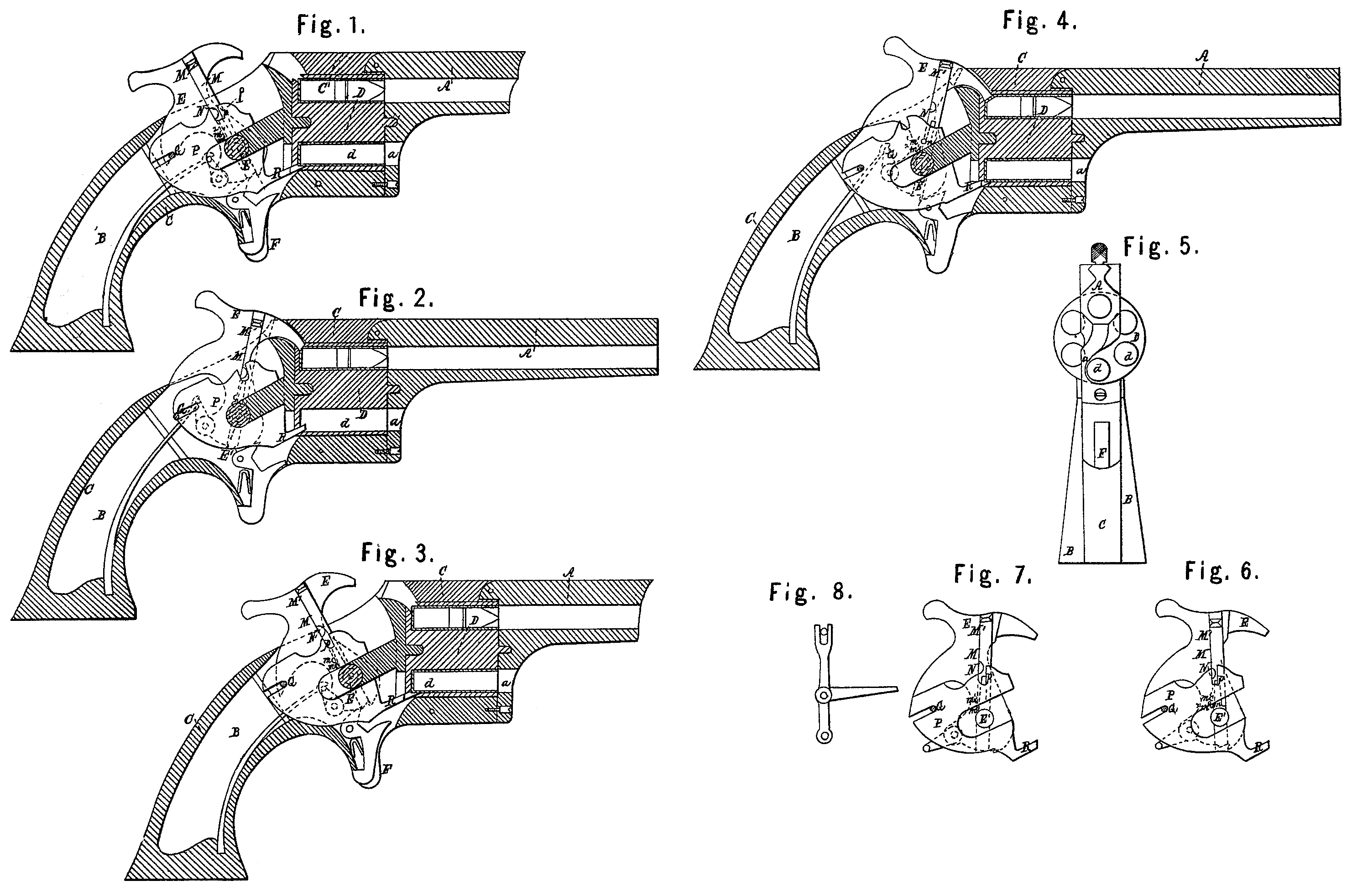
Figure 1 is a longitudinal section of a pistol With my improvements, in which the hammer is up and the slide in position to operate my invention. Fig. 2 is a similar view after the pistol has been fired and the cartridge ejected. Fig. 3 is also a longitudinal section with the hammer up and the slide M raised, or in a position which renders my invention inoperative. Fig. 4 is a similar view after the pistol has been fired. Fig. 5 is a front view. Fig. 6 is a side elevation of the slides in my invention, together with the hammer, detached from the other parts of the pistol, and in a condition to eject a cartridge if applied in a fire-arm. Fig. 7 is a similar view of my invention, with the parts arranged so as to be inoperative. Fig. 8 is another form of some of the parts.
Similar letters of reference indicate like parts in all the figures.
A is the barrel; B, the stock or handle; C, the intermediate case, of brass or other suitable material; D, the cylinder; d, the chamber or holes in which the cartridges are received.
The hammer E is adapted to strike through apertures (represented in the sides of the cylinder) and to explode the cartridge by a blow in that direction, as is frequently practiced in that class of arms.
The trigger F operates, in its relation to the cock, mainspring, &c., in the ordinary manner.
All the parts above described are constructed and arranged in the ordinary manner, except that the cavity a in the bottom of the piece A, and through which the cartridges are introduced and discharged, is arranged with its open side on the left instead of, as usual, On the right side of the pistol. The purpose of this is to allow the cylinder to be turned in case my mechanism shoulds fail to throw out the cartridge entirely clear of the cylinder.
M is a slide fitted in a groove in the right side of the cock E. The lower end of M is split, as represented, and its elasticity allows the branches thus produced to spring together slightly when necessary. On the outer face of one of these branches is a nib or spur, m, which is adapted to fit into either of the two recesses in m’ m^2 the side of the groove.
M is a face projection or head on the upper extremity of the slide M, and which is adapted to receive the pressure of the thumb-mail or other convenient means for pushing the slide M forcibly upward or downward, as required.
N is a spur which projects from the face of the slide M and performs a very important function. The whole purpose of the slide M and its accessories is to support this spur N and move it upward and downward and hold it in the required position, so that it shall be carried on the hammer E at a higher or lower elevation, as required.
P is a sliding plate, adapted to slide on the center stud, E’, and to be guided by the rear pin, G. Deep notches or slots having parallel sides are formed in the plate P to receive these studs E’ and G, and guide the plate so that it shall move forward and backward in a slightly-inclined path without liberty to turn around in either direction.
A deep notch, p, in the upper side of the plate P, is adapted to receive the spur N when the latter is in its lower position; but when the spur is elevated by forcing the slide M upward, then the spur N is entirely out of the notch p.
A stout thrusting pin or arm, R, extends forward from the lower edge of the plate B. It is of hardened steel, and is adapted to enter the hole in the lowermost of the chambers, d, and push out the cartridge or whatever is therein contained.
When the slide M is depressed the notch p receives the spur N and compels the plate P to traverse backward or forward, moving backward when the hammer E is drawn back or cocked, and moving forward when the hammer moves forward.
In operating the pistol for firing the slide M is simply forced up in its groove, and the pistol then operates in all respects like ordinary pistols, the plate P being held at rest by friction in such position that the thrusting-pin is entirely clear of the cylinder. In this condition the cylinder is revolved by the ordinary mechanism and the cartridges are successively exploded by the hammer.
When it is desired to remove the cartridges the slide M is forced down, the pin or spur N enters the notch p, and now the plate P moves backward as the hammer is cocked, and moves forward with a high velocity if the hammer is allowed to strike it at its ordinary rate. When so operated the thrusting-pin R strikes the cartridge which is in line with it, and starts it forward with so great a velocity that it is usually projected to a distance of several feet from the pistol. The hammer may be lowered slowly if desired, in which case the action will be less violent; but in either case the cartridge, whether a fresh one or one containing powder and ball, or simply an empty shell, will be started from its place and moved forward in the cylinder to an extent nearly equal to the traverse of the slide P. I prefer to operate the hammer freely and throw the shells or cartridges entirely clear of the pistol at a single operation.
This form of the invention above described is very simple, and requires the addition of only two pieces— viz., the slide M and plate P, with their several attachments, the plate P being adequately held by friction against accidental movements when not required, by making it very slightly warped or bent, so as to act as a Spring in keeping up a gentle and reliable friction against the sides of the casing. I propose, if required, to make this plate P entirely plane, and induce friction by an additional spring, (not represented,) which shall press against Some convenient part of either face.
When my invention is applied to muskets or any arms allowing considerable length for the plate P, I propose to carry the pin G. backward as far as may be, and to a proportional extent the plate P, so as to get a longer bearing for guiding and controlling the position of the plate.
I can employ a lever centered at a point below and having an open fork or notch at its upper end to receive the pin or spur N, instead of the plate P. In such case the arm or thrusting-pin R is linked or hinged to the lever at some point intermediate between the notch p and the fulcrum of the lever. This arrangement is indicated in Fig. 8. It gives a lower velocity to the shell of the cartridge on ejecting it; but I prefer the plate P and its attachments, as above described.
The thrusting-arm R on the plate P, or an equivalent sliding device, need not necessarily be in the same plane as the general surface of the plate. It may be so far removed to either side and mounted at such an elevation as to strike into either of the other chambers instead of into the lowermost chamber in the cylinder D. In such case the direction of motion of the part P may be correspondingly changed, so that the arm R shall enter the chamber in a proper direction.
I do not confine myself to the precise forms of the parts herein described. They are capable of various modifications, which will be obvious to mechanics. My invention may be operated with some success without the nibs M, and by providing other suitable means for holding the plate M in its elevated or depressed position on the hammer. Or, again, the pin or spur N, which performs the important function of communicating motion from the hammer to the thrusting mechanism, may be mounted on the hammer otherwise than on the slide M. It may, for example, be fixed on a lever turning by some suitable mechanism on the hammer E, so that when the lever is depressed the pin N shall communicate motion to the other parts, and when it is elevated it shall be of no effect, the same as above described. There may also be any number of intermediate levers, or other well-known mechanism, to communicate motion from the hammer E to the thrusting-arm R; but I prefer the simple construction as described.
Having now fully described my invention, what I claim as my improvement in fire-arms, and desire to secure by Letters Patent, is as follows:
In revolving fire-arms substantially of the character herein described, the employment of a movable part adapted to operate the ejecting mechanism or to have it unaffected by the movements of the hammer, substantially in the manner and for the purpose herein set forth.
GEO. G. CROWELL.
Witnesses:
C. M. Ryan,
W. M. Ryan.