
US 56466
UNITED STATES PATENT OFFICE.
WILLIAM TIBBALS, OF SOUTH COVENTRY, CONNECTICUT.
IMPROVEMENT IN REVOLVING FIRE-ARMS.
Specification forming part of Letters Patent No. 56,466, dated July 17, 1866.
To all whom it may concern:
Be it known that I, William Tibbals, of South Coventry, in the county of Tolland and State of Connecticut, have invented certain new and useful Improvements in Revolving Fire-Arms; and I hereby declare the following to be a full, clear, and exact description thereof, reference being had to the accompanying drawings, and to the letters of reference marked thereon, making part of this specification, in which—
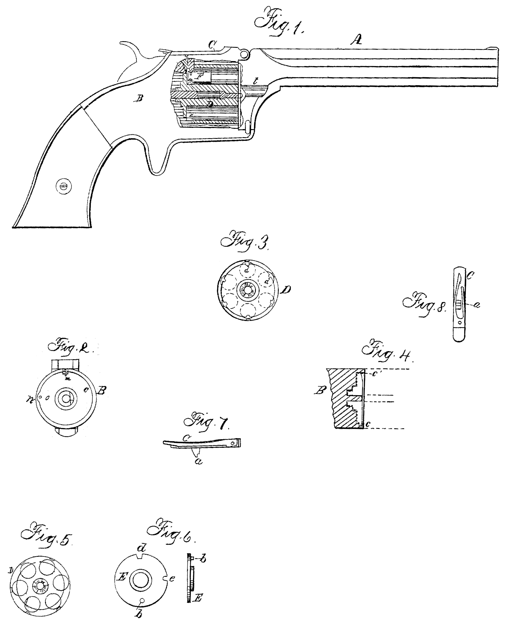
Figure 1 is a side elevation of my improved arm having a part broken away for the purpose of showing the internal arrangement the parts. Fig. 2 is a front-end view of the breech-block; Fig. 3, a rear-end view of the cylinder. Fig. 4 is a longitudinal section of the breech; Fig. 5, a rear view of a cylinder bored through, and Fig. 6 a rear and also a side view of a recoil-plate to be used with the cylinder shown in Fig. 5; and Figs. 7 and 8 are views of the anvil to be used in my improved arm.
The nature of my invention consists in constructing an arm adapted to the use of a peculiarly-constructed metallic cartridge described in my application for a patent on the same, filed here with; and my improvement consists more especially in a cylinder having a portion of its outer surface cut away at the rear, and in providing an inwardly-projecting flange on the breech to hold the cartridges in chambers, and also in a movable anvil to be used in connection there with.
To enable others skilled in the art to construct and use my invention, I will proceed to describe it.
A represents the barrel, and B the breech-frame, of an ordinary revolver. D represents a cylinder having its rear end closed, and having its rear portion turned off of smaller size, as shown in the section in Fig. 1, and also in the rear view in Fig. 3. This rear portion is cut away, so as to leave a portion of each chamber open on the side for a short distance at the rear, in order that when the cartridge F is inserted therein its side at the rear end shall be exposed for a distance equal to the width of the anvil a, as shown in Fig. 1; or, if preferred, the cylinder D may be bored entirely through, as shown in Fig.5, its rear portion being turned off, as described, and its rear end then closed by the plate or disk E, (shown in Fig. 6,) a pin, b, serving to attach the plate E to the breech and prevent it from turning with the cylinder, so as to keep the notch d in position for the hammer to strike through and hit the cartridge. When this style of cylinder is used the plate E is inserted so as to bring the notch e opposite the hole o in the breech, (see Fig. 2,) to permit the insertion of a pin or rod for pushing out the exploded shells, as hereinafter explained.
The front face of the breech or recoil block is recessed to receive the smaller portion of the cylinder, as shown in Figs. 1 and 4, and at its front this recessed portion of the breech is provided with an inwardly-projecting flange, c, which enters the groove in the cartridge-shells when the latter are inserted in the cylinder, and thus holds them in place and keeps them from dropping out when the arm is held muzzle down. This flange c, of which a front view is shown in Fig. 2, is cut away on the right-hand side, as shown at n, Fig. 2, so as to permit a cartridge to be shoved back into place in its chamber when at that particular position, it being obvious that the flange c will prevent the cartridge from being shoved home to its position when inserted at any other point than n.
In the center, at the top of the flange c, an opening is made, as shown in Figs. 2 and 4 of sufficient width to permit the anvil a to enter therein and drop into the groove in the neck of the cartridge, in front of the flange thereof, as shown in Fig. 1. This anvil a is attached to the pivoted piece C, which is pivoted to the frame directly over the cylinder, in such a position that when the hammer is raised its nose hits against and raises the rear end of C, there by raising the anvil a out of the groove in the cartridge, and thus permits the cylinder to revolve freely.
It is obvious that the flange C may be extended entirely around, except at n, instead of being cut away at the top, in which case the flange will serve as an anvil, thus dispensing with the movable anvil a; but I prefer the arrangement previously described, for the reason that when the flange of the cartridge is struck by nose in of the hammer it is liable to be expanded, and thus wedge the cylinder fast, preventing it from revolving.
By using the anvil a, which is raised out of the groove of the shell after the latter has been struck by the hammer, the cylinder is left free to revolve with ease.
The breech-block B, near n, as shown in Fig. 2, has a hole, o, bored through it in such a position as to be in line with the notches d in the rear of the cylinder as the latter is rotated, so as to bring the notches d opposite it successively. By inserting a small rod or pin in this hole o the empty shells can be pushed forward out of the cylinder one at a time, a groove, t, being cut in the side of the frame, in front of the cylinder, in line with the hole, as shown in Fig. 1. The cartridges are also inserted, one at a time, at the same point, the groove t permitting them to enter the chamber of the cylinder when in line there with.
It will be observed that the flange c is made slightly thicker at the point c’, (see Fig. 4.) which is done for the purpose of insuring the cartridge being drawn back, so as to cause its flange to enter behind the anvil a without fail.
It will be understood that the point m of the hammer strikes the flange of the cartridge, which contains the fulminate, directly in the rear of the anvil a, the flange being thus compressed between the anvil and the hammer.
By these means I am enabled to use a cartridge having its fulminate in an annular flange or projection of no greater diameter than the body of the shell, and which can, therefore, be inserted at the front of the chamber, and used in a cylinder which is not bored through.
Having thus fully described my invention, what I claim is—
1. Recessing the front face of the breech B to receive the smaller rear end of the cylinder D, when said recess is provided with the annular flange c, substantially as shown and described.
2. The removable anvil a, or its equivalent, when constructed and arranged to operate as and for the purpose set forth.
3. The annular flange c, or its equivalent, whether used with or without the anvil a, for the purpose of holding the cartridges in the cylinder, as described.
WILLIAM TIBBALS.
Witnesses:
Brigham Payne,
Robt. J. White.