
US 44363
UNITED STATES PATENT OFFICE.
S. W. WOOD, OF CORNWALL NEW YORK.
IMPROVEMENT IN REVOLVING FIRE-ARMS.
Specification forming part of Letters Patent No. 44,363, dated September 20, 1864.
To all whom it may concern:
Be it known that I, S. W. Wood, of Cornwall, in the county of Orange and State of New York, have invented a new and Improved Revolver or Revolving-Chamber Pistol; and I do hereby declare that the following is a full and exact description thereof, reference being had to the accompanying drawings, making part of this specification—
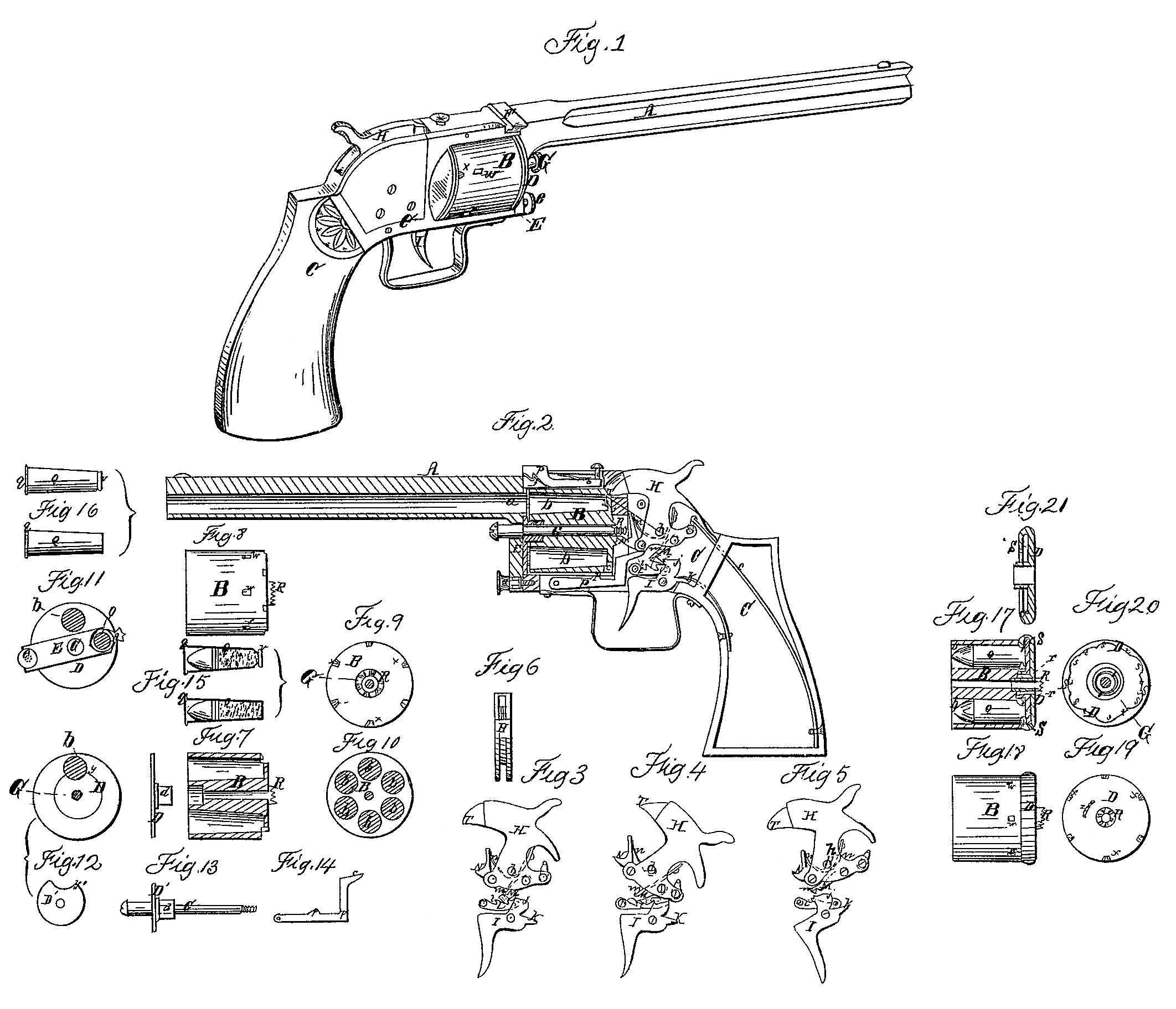
Figure 1 being a view in perspective of the pistol complete; Fig. 2, a central longitudinal vertical section thereof; Fig. 3, an elevation of the lock, representing the hammer as at half-cock; Fig. 4, a corresponding view of the same, representing the hammer at full-cock; Fig. 5, a similar view, represented as at discharge; Fig. 6, an edge view of the hammer; Fig. 7, a central longitudinal section of the cylinder through two of its chambers; Fig. 8, a side view of the cylinder; Fig. 9, a rear view there of; Fig. 10, a front view thereof; Fig. 11, a front view of the barrel, cylinder, and cap-plate, (full size of cylinder,) representing the barrel as turned aside from the front of the discharge chamber for the purpose of loading and for expelling the empty cartridge cases; Fig. 12, a front view of the cap-plate (two forms) in front of the cylinder; Fig. 13, an edge view thereof, (of one form,) showing it on the pin on which the cylinder revolves, and on which the barrel is turned; Fig. 14, a side view of the vibratory bar which locks the cylinder in position for the successive discharges from its chambers; Fig. 15, a central longitudinal section of the cartridge used, showing two forms thereof; Fig. 16, a side view of the same; Fig. 17, a central longitudinal section of a modified arrangement of the cylinder and the retaining cap-plate; Fig. 18, a side view of the same; Fig. 19, a rear view of the cap-plate separately; Fig.20, a front view of the cap-plate on the pivot-pin; Fig.21, a central section of the cap-plate.
Like letters designate corresponding parts in all of the figures.
The barrel A, cylinder B, and stock C constituting the main essential parts of the pistol, all the other parts are accessory thereto, a description of the construction, arrangement, and functions of which will include a complete specification of my improvements.
My invention especially contemplates the employment of metallic-case cartridges, the fulminate being contained in the rear end thereof, so as to produce the discharge by a simple blow of the hammer against a part of the case in immediate contact with or opposite to some of the said fulminate, the empty case remaining in the cylinder after the discharge. In the use of these metallic case or equivalent cartridges in a revolving cylinder my first principal improvement consists in loading the cylinder-chambers at the front end, the rear end of the chambers being permanently closed, except small nicks or apertures to give access to the face of the hammer, and in retaining the cartridges in the chambers by a cap-plate or its equivalent applied at the front end of the cylinder or toward or at the rear thereof, so as to hook around or bear against some flange or projection of the cartridge-case. The chambers b b of the cylinder are made somewhat flaring or conical, the mouth or front end being of greatest diameter, and the cartridges Q, Q are made of a corresponding taper form, fitting the chambers closely when completely inserted therein, but loosely as soon as started out of the chambers, even a very short distance. The obvious use and advantage of this construction will be at once understood as enabling the cartridge-cases to be withdrawn or driven out with perfect ease when once started from their first position, and this however closely the cartridge-cases may be packed in the chambers by the discharge. The degree of taper may be about as represented— more or less, as found preferable. This improvement constitutes another feature of my invention.
As I contemplate two modifications of the method of retaining the cartridges in the cylinder-chambers otherwise than by the mere friction or pressure of the cartridges themselves against the sides of the chambers, so also corresponding modifications of the general form of the cartridge-cases are to be produced.
The simplest form of cartridge to be used with a front cap-plate for retaining them in the chambers is indicated in the lower representation, respectively, in Figs. 15 and 16, and for use with a rear retaining-plate is indicated in the upper representation of the same figures. In both modifications here the metallic case lines the whole interior of the chamber, and also has a projecting flange or lip, q, outside, so as to bear or rest against the front end of the cylinder. There is a space, g, Fig. 2, between the front end of the cylinder and the rear end of the barrel and of the cap-plate of sufficient width to admit this flange q of the cartridge. In the cartridge-case not only is the powder but the entire bullet is inserted, the case furnishing a lining for the chamber, and its interior diameter at the front end being about the same as that of the bore a of the barrel.
In the application of the mode of retaining the cartridges in their chambers at the front end I employ a thin cap-plate, D, which shall partially or wholly cover the mouths of the chambers, except the uppermost one, that being directly in line of the bore a of the barrel, and requiring to be always open. The plate may cover the whole front end of the cylinder B, as shown at D in Figs. 1 and 11, leaving a round aperture, y, to furnish communication between the bore a of the barrel and the uppermost or discharging chamber; or the plate may be only large enough to partially cover the ends of the chambers and cartridge-cases, as at D’, Figs.12 and 13, leaving a communicating notch, y’, therein. The plate requires to be held in a fixed position, moving neither with the cylinder nor with the barrel when either is turned on the common axis or pin G thereof. Hence, the pin being screwed fixedly in the stock of the pistol, the cap-plate is secured immovably thereto, and I generally effect this by extending a hub, d, of the plate inward and around the pin G, and applying a tightening-screw, as indicated in Figs. 2 and 13. This cap-plate, when of full size, completely hides the cartridges and chambers from outward view.
The mode of applying the cup or retaining-plate D at the rear end of the cylinder is substantially illustrated in Figs. 17, 18, 19, 20, and21. The plate is rotated on an axis forming a part or fixture of the cylinder, so as to move round there with, but also have a turning movement to a certain extent on said axis independent of the cylinder. This movement may be conveniently effected by attaching a coiled spring, r, at one end to the inside of an aperture or flange of the cap and at the other end to the axis on which it turns. This spring retains the cap-plate in the required position in relation to the cylinder, but allows it to be turned aside as far as required by yielding. The extent of the movement is limited by a pin on the cylinder and a slot in the plate, or their equivalents, as shown in Fig. 19. On the forward edge of the periphery of the plate a lip, S, is turned inward toward the center, leaving a narrow space behind it. This lip is intended to hook around a bead or flange, v, formed on the rear edge of the cartridge-case, adapted to this purpose, as shown by the upper representation in Figs, 15 and 16, and also in Fig. 17, where the mode of retaining the cartridge by this lip is clearly indicated. The bead is of no larger diameter than the cartridge-case would be there if extended back without the bead, so that a neck must be formed just in front thereof. The lip S of the retaining-plate has a number of curved notches or depressions, s s, Fig.20, equal to and at intervals corresponding with the chambers of the cylinder, and of such positions, depth, and shape as to allow the beads of all the respective cartridges to pass back through when brought opposite to them by turning the cap D with the hand applied to its edges. Then the spring r turns the cap-plate back to and holds it in its normal position, or such that portions t t, Fig. 20, of the lip S, intermediate between the depressions s s, shall come in front of the beads v v of the cartridges occupying the necks thereof, and thus retain the cartridges in the chamber. When the empty cartridge-cases are to be removed from the chambers the retaining plate is again turned aside, so as to bring the depressions SS opposite to the beads v v. With this mode of retaining the cartridges in the chambers the cartridge-cases need not reach the whole length of the chambers nor have the flanges q q , but may have simply the ordinary length, as indicated in Fig. 17.
The fulminate is placed in the rear end of the cartridge, (in the bead v, when employed.) and the explosion is produced by a blow of the hammer H against the cartridge, as usual with metallic-case cartridges. Nicks or notches x x are made in the rear edge of the cylinder B, opening into the chambers, to enable the face T of the hammer to reach the cartridges. When the rear cap, D, is used, there are corresponding notches also made therein.
The barrel A is secured to the frame by a projection, E, through which passes the pin G of the cylinder B, and is secured to the stock by means of this pin and by a spring-hook, F, pivoted to the frame and catching into a notch, f, Fig. 2, of the barrel, and by a screw, e, or its equivalent, which extends through the projection E and into a part of the frame below the cylinder. The hook F and its notch f allow the barrel to turn freely, and the screw e keeps it in position. Then by withdrawing or detaching this screw from the frame it allows the barrel to be turned on the axis-pin G out of line with the upper cylinder-chamber and of the hole or notch y of the cap-plate, (if used in front,) as indicated in Fig.11. Thus free access can be had to the chambers of the cylinder through the aperture y of the cap-plate, when used there, for the purpose of inserting the cartridges into the chambers; but this feature of my invention, turning the barrel. A out of line with or from the front of the discharging-chamber of the cylinder, is designed more especially to allow another of my improvements— namely, expelling the empty cartridge-cases by the hammer itself, for when the barrel is away from the front of the discharging-chamber, or one in line with the hammer, the cap-plate D being stationary, the hole or notch y allows the free discharge of the empty cases. I then operate the hammer H just as when firing the pistol, and the blows thereof against the empty cases force them out of the chambers successively as the cylinder B is by the same action brought round to the hammer. The conical shape of the chambers and cartridges by setting the cartridge-cases free as Soon as once started even slightly from position in the chambers so facilitates this action that the blows of the hammer cause them to fly out of the chambers to a considerable distance. The empty cases having been expelled, the chambers may be at once reloaded, and the barrel then brought back to position and secured by the screw e or its equivalent. This is an exceedingly simple, effectual, and rapid method of performing the required services.
I construct the lock and its adjuncts with some peculiarities. The hammer H, pivoted at h, Fig. 2, with its mainspring c, may thus far be as usual; but to a part thereof, behind its pivot h, is pivoted a hook, M, which catches into notches l l in the edge of a fixed ratch or rack bar, L, and holds thereby the hammer at half-cock or full-cock, respectively. This hook or detent is held down to the ratch by a spring, m, or its equivalent. The hook of the detent is wider than the ratch Li, so that it projects on one side thereof. The upper end of the trigger I moves close along the ratch L, so that it comes in contact with the projection of the detent-hook, and it has a point or toe, i, which will catch into the hook of the detent as the trigger is pulled. This action of the trigger raises the hammer to full-cock, or until a heel projection, j, of the trigger comes into contact with the detent, and by its wedge or cam action lifts the same till it disengages its hook from the point of the trigger and allows the hammer to descend. Thus simply does the pulling of the trigger raise the hammer and let it descend again. When the hammer is raised by hand only does the detent M hooks into the notches of the ratch, so as to hold the hammer at either half-cock or full-cock, and this action is entirely independent of the trigger; but on pulling the trigger the heel j also strikes the detent when hooking into the ratch and raises it therefrom, causing the hammer go descend. This simple arrangement is sure and effective. The movement of the hammer H turns the cylinder B by means of a pawl, N, pivoted to the hammer in front of the center h and acting against a set of ratchet-notches, R, on the rear end of the cylinder, so arranged that the raising of the hammer will just turn the cylinder the angular distance between its several chambers. The pawl is held forward to the cylinder by a spring, n. The cylinder is held in position after being turned by the pawl N by means of a vibratory bar, P, having a projection, p, which ascends into holes or notches w at in the surface of the cylinder. The bar P is forced upward by a spring, u, beneath, and it is forced down so as to clear the notches w w by the positive action of a protuberance of the hammer when descending, as indicated in Fig. 2. As soon as the face T of the hammer enters the notches x x of the cylinder it retains it in position.
The improvements described above are also applicable to carbines and other light small arms.
What I claim as my invention, and desire to secure by Letters Patent, is—
1. Loading the cartridges into the chambers of the cylinder and expelling the empty cartridge-cases therefrom when the said chambers are inline with the hammer or in the same position as when the discharge takes place.
2. Expelling the empty cartridge-cases by the blows of the hammer, substantially as here in specified.
3. Turning the barrel aside from its discharge position, in combination with a front loading cylinder, for the purpose of enabling the cartridges to be inserted into and the empty cartridge-cases to be expelled from the chambers when in line with the hammer, substantially as herein set forth.
S, W. WOOD.
Witnesses:
L. F. Bull,
J. S. Brown.