
British 880
LETTERS PATENT to William Clark, of 53, Chancery Lane, in the County of Middlesex, Engineer & Patent Agent, for the Invention of “ Improvements in Fire-arms.”—A communication from abroad by the u Starr Arms Company,” of the City, County, and State of New York, U.S.A.
Sealed the 3rd September 1860, and dated the 7th April I860.
PROVISIONAL SPECIFICATION left by the said William Clark at the Office of the Commissioners of Patents, with his Petition, on the 7th April 1860.
I, William Clark, of 53, Chancery Lane, in the County of Middlesex, Engineer & Patent Agent, do hereby declare the nature of the said Invention for “ Improvements in Fire-arms,” to be as follows:—
This Invention relates to revolvers having their chambers or bores arranged parallel with each other, and with the axis about which they revolve.
It consists in an improved construction of the frame which contains the chambered cylinder, whereby provision is made for opening it for the purpose of removing and replacing the cylinder, and whereby when it is closed it is made very strong & rigid.
It also consists in an improved construction of the dog and ratchet, through which the revolution of the chamber is effected by the act of cocking, whereby the said dog is made to stop the cylinder in a proper position for firing when the hammer is cocked.
It also consists in a certain construction of and mode of applying the central shaft of the chambered cylinder for the purpose of preventing the said cylinder from coming into contact with the rear end of the fixed barrel in its revolution, and of securing the said shaft in place.
It also consists in so applying a cocking lever under the stock or frame of the piece, in combination with a separate trigger for firing, that the said trigger may be operated by the continued pull of the said cocking lever beyond the the position at which it effects the cocking.
It also consists in an improved mode of combining the cocking lever with the hammer to effect the cocking only, or the cocking & firing, by means of the said lever.
It also consists in the employment in combination with the cocking lever and trigger of a shifting stop capable of being so set as to enable the firing to be effected either by the continued back pull of the cocking lever after it has arrived at the position for cocking, or by touching the trigger after the hammer has been cocked.
It also consists in applying the springs of the cocking and revolving dogs within a circular grove in one side of the hammer, but where they occupy no otherwise available room in the cock.
It also consists in so constructing the cocking lever that the said lever may be capable of cocking the cylinder by its backward movement when firing is effected by the said lever, and of cocking it by its forward movement when firing is effected by the trigger.
And it further consists in providing for the easy application of the percussion caps to the nipples by making in the stationary recoil plate or shield on that side of the piece where the caps are to bo applied a double guide channel to guide the forefinger, and a narrower one to guide the caps to the nipples.
SPECIFICATION in pursuance of the conditions of the Letters Patent, filed by the said William Clark in the Great Seal Patent Office on the 5th October 1860.
TO ALL TO WHOM THESE PRESENTS 8HALL COME, I, William
Clark, of 53, Chancery Lane, in the County of Middlesex, Engineer & Patent Agent, send greeting.
WHEREAS Her most Excellent Majesty Queen Victoria, by Her Letters Patent, bearing date the Seventh day of April, in the year of our Lord One thousand eight hundred and sixty, in the twenty-third year t of Her reign, did, for Herself, Her heirs and successors, give and grant unto me, the said William Clark, Her special licence that I, the said William Clark, my executors, administrators, and assigns, or such others as I, the said William Clark, my executors, administrators, and assigns, should at any time agree with, and no others, from time to time and at all times thereafter during the tenp therein expressed, should and lawfully might make, use, exercise, and vend, within the United Kingdom of Great Britain and Ireland, the Channel Islands, and Isle of Man, an Invention for ” Impbove-ments iif Fibe-arms,” a communication from abroad by the “ Starr Arms Company,” of the City, County, & State of New York, U.S.A., upon the condition (amongst others) that I, the said William Clark, my executors or administrators, by an instrument in writing under my, or their, or one of their hands and seals, should particularly describe and ascertain the nature of the said Invention, and in what manner the same was to be performed, and cause the same to be filed in the Great Seal Patent Office within six calendar months next and immediately after the date of the said Letters Patent.
NOW KNOW YE, that I, the said William Clark, do hereby declare the nature of the said Invention, and in what manner the same is to be performed, to be particularly described and ascertained in and by the following statement, reference being had to the Sheet of Drawings hereunto annexed, and to the letters and figures marked thereon (that is to say):—
This Invention relates to revolvers having their chambers or bores arranged parallel with each other and with the axis about which they revolve.
It consists in an improved construction of the frame which contains the chambered cylinder, whereby provision is made for opening it for the purpose of removing and replacing the cylinder, and whereby when it is closed it is made very strong and rigid.
It also consists in an improved construction of the dog and ratchet through which the revolution of the chambered cylinder is effected by the act of cocking, whereby the said dog is made to stop the cylinder in a proper position for firing when the hammer is cocked.
It also consists in a certain construction of and mode of applying the central shaft of the chambered cylinder for the purposes of preventing the said cylinder from coming into contact with the rear end of the fixed barrel in its revolution, and of securing the said shaft in place.
It also consists in so applying a cocking lever under the stock or frame of the piece, in combination with a separate trigger for firing, that the said trigger may be operated by the continued pull of the said cocking lever beyond the position at which it effects the cocking.
It also consists in an improved mode of combining the cocking lever with the hammer to effect the cocking only, or the cocking and firing by means of the said lever.
It also consists in the employment in combination with the cocking lever and trigger of a shifting stop capable of being so set as to enable the firing to be effected either by the continued back pull of the cocking lever after it has arrived at the position for cocking, or by touching the trigger after the hammer has been cocked.
It also consists in applying the springs of the cocking and revolving dogs within a circular groove in one side of the hammer butt, where they occupy no otherwise available room in the lock.
It also consists in so constructing the cocking lever that the said lever may be capable of locking the cylinder by its backward movement when firing is effected by the said lever, and of locking it by its forward movement when firing is effected by the trigger.
And it further consists in providing for the easy application of the percussion caps to the nipples, by making in the stationary recoil plate or shield on that side of the piece where the caps are to be applied a double guide channel, that is to say, a wide channel to guide the forefinger, and a narrower one to guide the caps to the nipples.
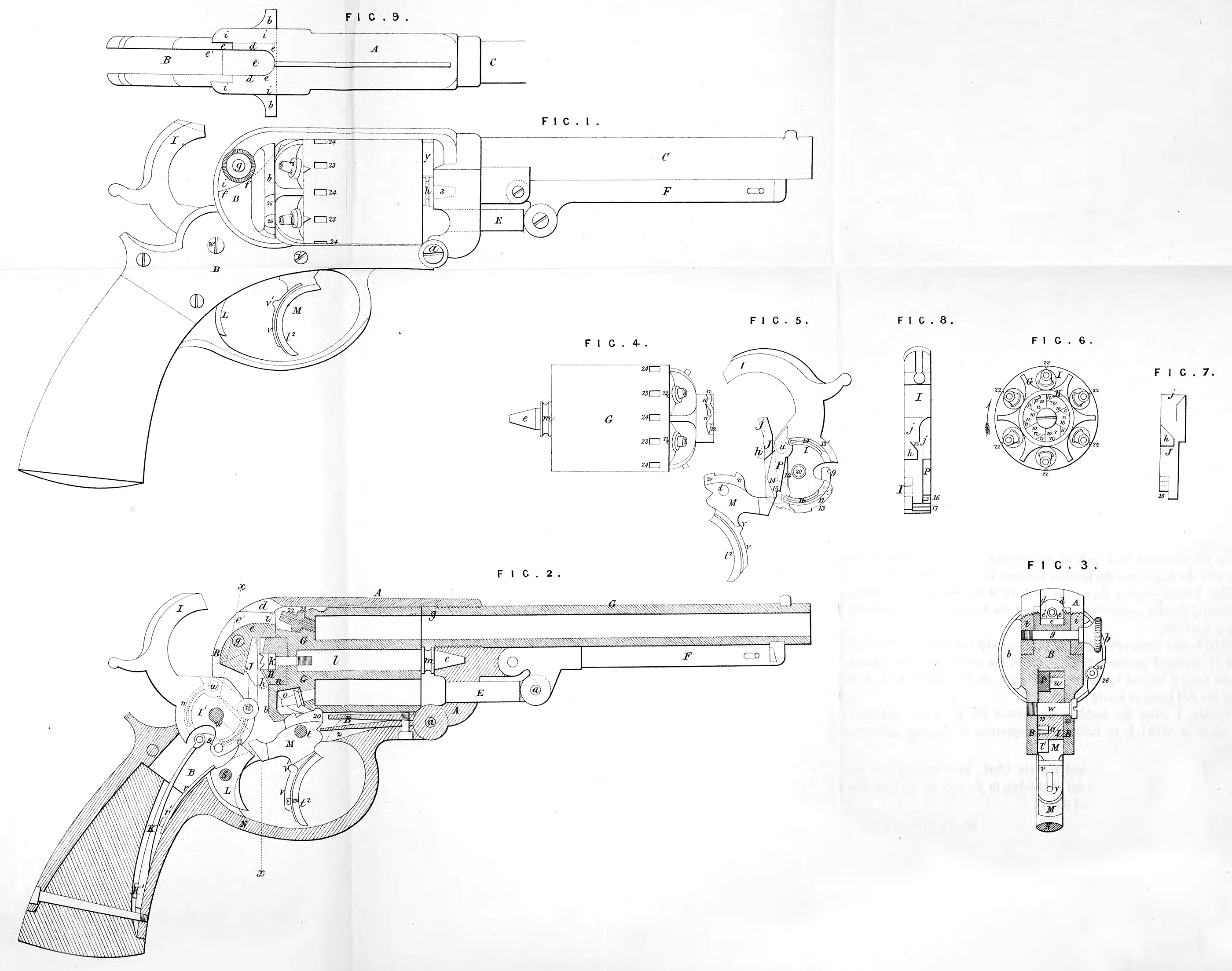
The Invention is illustrated in the accompanying Drawings, in which Fig. 1 is a side view of a pistol with my improvements; Fig. 2 is a longitudinal section of the same; Fig. 3 is a transverse section of the same in the line x, x, of Fig. 2; Fig. 4 is a side view of the many chambered cylinder; Fig. 5 is a side view of the mechanism of the lock ; Fig. 6 is a back view of the cylinder; Fig. 7 is a front view of the dog by which the revolving of the cylinder and the stopping of the same in proper position are effected ; Fig. 8 is a front view of the hammer with the cocking and revolving dogs attached ; Fig. 9 is a top view of the cylinder frame. Similar letters & numbers of reference indicate corresponding parts wherever they occur in the several Figures.
A, B, represents the cylinder frame, having the stationary barrel C screwed into the upper part of its front, and having attached the stock D. This frame is made in two pieces connected together at the bottom of its front part by a hinge-joint a. The piece A, which constitutes the front and upper part of the said frame, has attached to it the stationary barrel C, and the rammer E, F, and contains the journal for the front journal c of the revolving cylinder G. The piece B, which constitutes the back and lower parts of the said frame, has formed upon it the stationary recoil shield b, b, and extends back far enough to receive within it the principal parts of the lock and the mechanism for cocking the hammer and revolving the cylinder, and it has formed in the centre of the shield b9 b9 a bearing for the outer cylindrical [portion of the circular ratchet H of the cylinder G, which constitutes the back journal of the said cylinder. In the rear end of the piece there is formed a mortise d9 d9 for the hammer I to pass through to strike the caps on the nipples of the cylinder, and the said piece is extended downwards from this mortise in the form of two cheeks i, i9 which receive a tenon e, formed on the piece B behind the recoil shield; the said cheeks hooking over the back of the recoil shield, and resting against a shoulder/, on each side of the tenon e9 when the frame is closed, and the said cheeks and the tenon being secured together by a pin g9 passing through them and screwing into one of the cheeks. The principal object of the pin is to prevent the frame opening by a movement of the hinge-joint a, and the strain which comes on the frame in firing is received by the hook-like cheeks t, t, and met by the shoulder/, against which they bear. This method of constructing and fitting the two parts of the frame A, B, together, makes it very rigid and strong in every direction. The exterior of the tenon e9 has in it a groove e1, for the hammer to enter when it falls. The circular ratchet H of the cylinder has its notches n, n\ n\ n\ cut in the back with parallel sides,, ns shown in the back view Fig. 6, and with their bottoms sloping in such a manner as to make them deepest towards the circumference as shown in Fig. 2, the side 10 of each against which the revolving dog J acts to produce the revolution of the cylinder being radial to the centre. The cutting of the notches with parallel sides as shown in Fig. 6, leaves projections 11, of triangular form between the several notches, and these projections serve as stops for a tooth h9 attached to the revolving dog J to act against for the purpose of stopping tl*e cylinder from revolving farther with one movement of the hammer than is sufficient to present a new chamber opposite to the barrel, and to make it stop with the chambers in line with the barrel. The revolving dog J is’ attached to the front part of the butt of the hammer, and has the stop tooth hr arranged on the opposite side of the centre of its face to the tooth j9 which as the hammer is drawn back to be cocked, acts upon the ratchet to produce the revolution, and much lower down than the said tooth* as shown in the Figures 5 & 7. The locking tooth h is bevelled, so that its most prominent part is at the bottom, as shown in Fig. 2, and its width is such that it will just fit the parallel notches of the ratchet H, one of whieh is always in the vertical position of n%9 in Figure 6, to receive the said tooth when a chamber is in line with the barrel. As the revolving dog terminates its upward movement with the arrival of the hammer at full cock, the tooth h by its action against the projections 11, at the right side of the vertical notch prevents any further revolution of the cylinder. The triangular projections 11 on the cylinder are bevilled off as shown in Fig. 2, towards the sides 10 of the notches, that they may pass the rising stop tooth h, in the revolution of the ratchet and cylinder. The revolving tooth j is made with a slightly rounded sloping edge, as shown in Fig. 1, and from this edge it has a backward slope in a downward direction. This form of the said tooth j\ combined with the sloping form of the bottoms of the notches of the ratchets exhibited in Fig. 2, enables the said tooth, as well as the tooth h9 to stop the ratchet when the cylinder has moved far enough. The said tooth commences to act in the notches when they are severally in the position of the notch indicated as n\ in Fig. 6, and carries them to the upright position of that indicated as n9, and on the arrival of the notch in this position the said tooth has entered it so far as to prevent the stop 11 on the left hand side of the said notch from passing it For greater convenience of construction the ratchet H, though close to the rear of the cylinder G, is made of a separate cylindrical piece of steel fitted into a central countersunk recess provided in the rear of the cylinder to receive it. It is secured in its place by the countersunk head of a screw k, which screws into the rear end of the central arbor l of the cylinder, and which also serves to secure the said arbor in place. The front journal c of the cylinder is a portion of the arbor l, and the said arbor is formed with a collar m, at the back of this journal, which collar is held up close to the front of the cylinder by the screw k, aud which, when the cylinder is in its place and the frame A, JB, closed, abuts against the surface surrounding the bearing of the front journal of the cylinder, and so keeps the cylinder just clear of the rear muzzle y of the stationary barrel to permit it to revolve freely. The cylinder is held forward as close to the barrel as the collar m permits, by a shoulder o, o, surrounding the ratchet H, whose exterior portion, as has been herein-before stated, constitutes the rear journal, said journal working in contact with the stationary recoil shield b. The ratchet H is prevented from turning without the cylinder by a steady piny?, inserted through the ratchet into the cylinder. To provide for the easy insertion of the cylinder its front journal and the bearing therefore are made conical. The cylinder has its rear journal put into its bearing when the frame B, C, is open, and as the frame is closed up the taper front journal finds its way easily into its bearing.
The hammer I working on the pin w passing through the piece B of the frame has its butt I1 made substantially of the same profile form as the hammers of most other revolvers, and has the mainspring K applied to it substantially in the usual manner, with a stirrup connection q. The trigger L is applied to operate in a notch 13 of the hammer butt to lock the hammer in a cocked condition, as illustrated in Fig. 2, without the use of a separate sere. The cocking lever M is arranged in front of the trigger within the same guard piece N, which is so constructed and attached to the frame A, B, as to allow it to be removed with the mainspring, the trigger spring r, and the trigger, all of which are attached to it, the first two by screws K1 and r1, and the last by its fulcrum pin s. The cocking lever, which works upon a fulcrum pin f, passing through the lower part B of the frame, is constructed with a back-wardly projecting armt1, which effects the cocking of the hammer as its finger-piece t2 is pulled back, by being forced upward against the lower extremity of the lever-like dog P (see Figure 5), which is pivotted near its upper end to the front part of the hammer butt above the fulcrum pin w thereof. The upward pressure of the arm tl against the dog P causes the part of the said dog above its pivot u to be forced back against the back of a recess 12 that is formed in the hammer butt to contain the said dog, and the said dog is thus caused to assume a rigid condition relatively to the hammer, and the hammer to be forced back steadily by the action of the finger lever until it is cocked by the trigger falling into the notch 13. The firing may be effected either by the trigger or by the rocking lever, according as it is desired to take deliberate aim before every shot, or to fire several charges in rapid succession without so much accuracy of aim. In the former case the cocking lever must be prevented being drawn so far back as to allow the arm t1 to escape or pass clear of the dog P, and for this purpose I furnish the said lever with the shifting stop v, consisting of a piece of steel fitted to slide along the back of the finger-piece t2, and furnished with a projection v1, which, when the said stop is moved downward to the position shown in Figure 1, will come in contact with the guard piece N before the escape of the arm t from the dog P, and before the lever strikes the triggers. But in the other case the stop is shifted up to the position shown in Figure 2, so that when the finger-piece is drawn back it may enter the mortise provided in the frame A, B, for the cocking lever to work in, and so allow the said lever to move back far enough for its arm t1 to escape from the dog P, and for the back of its finger-piece to press back the trigger and let the hammer escape. The cocking lever has applied to it a spring z, whose duty it is to throw down the arm tl and throw forward the finger-piece t2 whenever the latter is relieved of the pressure of the finger. When the firing is to be effected by the trigger, the finger is removed from the cocking lever, and the latter allowed to descend before the trigger is pulled, and the arm tl is moved out of the way of the dog P before the latter is required to descend, but in firing by the cocking lever the dog P in its descent has to pass the elevated end of the arm tl> and to permit this room is left in the recess 12 of the hammer butt behind the said dog for the lower part of the said dog to move backward in passing the said arm, and the lower part of the front of the said dog is bevilled, as shown at 19 in Figure 5, and the hammer is thereby enabled to fall without obstruction. After the descent of the arm t1 the lower part of the dog P is caused to move forward again to a position for the arm i1 to catch it, the next time the cocking lever is pulled to cock the hammer, that is to say, to the position represented in Fig. 5, with: the part of the said dog above the pivot u resting against the back of the recess 12 in the hammer butt by means of a spring 14 attached to the hammer butt, and entering a notch in the said dog. The dog p is so fitted into the recess 12, which is made in one side of the hammer butt I1, and it has its pivot u so attached to it and fitted to a hole in the said butt, and the revolving dog J is so partly fitted into a recess within the recess 12, and has its pivot 15 so attached and fitted to a hole in the said butt that the said dogs are flush with the sides of the hammer butt, as shown in Figure 8, and the spring 14 of the cocking dog, and the spring 16 of the revolving dog are both so arranged within a circular groove 17 cut in one side of the butt I1, that neither of the said springs project from the hammer, which is thus enabled to be fitted snugly within a parallel sided groove 18 made in the part B of the cylinder frame, as shown in Figure 5, and all the mechanism is thus made very substantial without any of its parts occupying any unnecessary space in the frame, which is thus enabled to be made as nearly solid as possible, and the arm is thus enabled to be made very strong and durable. To provide for the locking of the cylinder to prevent its rotation while being fired, either by the cocking lever or by the trigger, the cocking lever is made with two upward projections on the upper part, viz., one, 20, in front of its fulcrum pin t, and another, 21, behind the said pin. When the lever is drawn back as far as is practicable, or even far enough to cock the hammer, the backward projection 21 enters one of a series of equidistant notches 22, 22, equal to the number of chambers in the rear portion of the cylinder, and locks the cylinder in the position in which its revolution which was effected simultaneously with the cocking haa been stopped by the tooth h on the dog J. The cylinder thus locked cannot be unlocked till the cocking lever is liberated by the finger, and hence must remain locked during the fall of the hammer in firing by the said lever. When the firing is to be effected by the trigger, the movement of the cocking lever, which takes when its finger-piece is liberated, brings the forward projection 20 on the said lever into one of a series of notches 23, 23, arranged in advance of but in line with the notches 22, 22, aud so locks it until the cocking lever is again pulled. In the movement of the lever from the notch 22 to that 23, the hammer remaining cocked, the cylinder remains locked by the teeth j and h on the cocking dog. Midway between the notches 23 there are arranged similar notches 24, which may be termed safety notches, for the purpose of receiving the tooth 20 of the cocking lever to lock the cylinder in a position in which no chamber is opposite to the barrel and no nipple opposite to the hammer, in which position of the cylinder any accidental discharge is impossible. To permit the cylinder to be so locked, the cocking lever is pressed back just far enough to withdraw the tooth 20 clear of it, and the cylinder is then turned to bring one of the notches 24 opposite the said tooth, and the trigger is then liberated. The double-guide channel provided in the stationary recoil plate or shield b to facilitate the capping is made in the right side of the recoil plate or shield b opposite to a position to which the nipples may be severally brought by turning the cylinder.
The outer channel 25 is made wide enough to receive the forefinger of the person who applies the caps, and the inner channel 26, which is in the middle of the outer one, is made wide enough to receive the caps, and both incline inward from the back toward the front of the plate or shield b. These grooves enable the way to the nipples to be felt, so that the caps may be applied in the dark, and also serve to guide the finger and the cap when the fingers are numbed by cold.
Having described the nature of this Invention, and the manner of performing the same, I declare that I claim as the Invention to be protected by the herein-before in parts recited Letters Patent, as follows:—
First, though I do not claim the construction of the cylinder frame of two pieces A, B, united by a hinge a at the point described, I claim the construction of the upper piece A with two cheeks i, t, to hook or lap over the back of the piece B on opposite sides of a tenon e provided on the latters, and to receive a pin g passing also through said tenon, substantially as herein described.
Secondly, I claim so constructing the tooth j of the revolving dog J, and the ratchet upon which it operates, that the said tooth is made to serve also as a stop to prevent the cylinder revolving too far, as herein described.
Thirdly, I claim furnishing the revolving dog J with an additional tooth A, applied and operating in combination with a ratchet, constructed substantially as herein described for the purpose set forth.
Fourthly, I claim securing the central arbor l of the cylinder, and the ratchet H thereof in their places by the same screw 1c, applied as described, and acting in combination with a shoulder.m on the pin, as set forth.
Fifthly, I claim keeping the cylinder out of contact with the barrel by means of a collar m of proper thickness, provided on an arbor l to which the cylinder is secured, and on which its front journal is formed, substantially as herein described.
Sixthly, I claim so applying a cocking lever in combination with a separate trigger for firing, that the said trigger may be operated by the continued pull of the cocking lever beyond the position at which it effects the cocking, substantially as herein described.
Seventhly, I claim the cocking dog P attached to the hammer butt by a pivot u above the fulcrum or centre of motion of the hammer, and otherwise applied, as herein described, in combination with a backwardly extended arm tl on the cocking lever, to effect either the cocking only, or the cocking and firing of the piece.
Eighthly, I claim in combination with a cocking lever and trigger, arranged and combined to operate substantially as specified, the employment of the shifting stop on the cocking lever, capable of being set to effect the discharge, either by the continued back pull on the cocking lever, or by touching the trigger with the finger after the hammer has been cocked, as described.
Ninthly, I claim applying the springs 14 & 16 of the cocking and revolving dogs within a circular groove 17 in one side of the hammer butt, substantially as herein described.
Tenthly, I claim constructing the cocking lever with two teeth or projections 20 and 21, arranged substantially as described, the one to lock the cylinder while the firing is effected by the trigger, and the other to lock it while it is fired by the said lever, as herein described.
Eleventhly, I claim the double-guide channel 25, 26, in the stationary recoil plate or shield 5, to facilitate the operation of capping, as herein described.
In witness whereof, I, the said William Clark, have hereunto set my hand and seal, this Fifth day of October, in the year of our Lord One thousand eight hundred and sixty.
Witness,
W. G. E. SWINNOCK,
53, Chancery Lane.
W. CLARK. (l.s.)