
British 899
LETTERS PATENT to John Rigby, of the City of Dublin, Ireland, ^Gun Maker, and William Nicholas Norman, of said City of Dublin, Gentleman, for the Invention of “ Improvements in Guns and other Fire-arms, and in Cartridges to be used therewith.”
Sealed the 4th October 1860, and dated the 10th April I860.
PROVISIONAL SPECIFICATION left by the said John Rigby and William Nicholas Norman at the Office of the Commissioners of Patents, with their Petition, on the 10th April 1860.
I, John Rigby, of the City of Dublin, Gun Maker, and I, William Nicholas Norman, of said City of Dublin, Gentlemen, do hereby declare the nature of the said Invention for “ Improvements in Guns and other Fire-arms, and in Cartridges to be used therewith,” to be as follows:—
Our Invention consists, first, in a particular form and arrangement of jointing the barrels to the breech in double or single breech-loading guns, by attaching a piece of metal to the under surface of the barrels at the back end ; said piece of metal has at the extremity towards the muzzle a strong stud, which passes through a hole in the breech-piece carried forward under the barrel to a convenient distance from the breech, and at the butt end a projection, which enters a slot made in the breech-piece; by this arrangement the barrels can be turned on the stud out of the line of the gun so as to bring their breech ends clear of the breech-piece & so permit the insertion of the cartridges, while upon bringing them again into their original position the projection before mentioned enters the slot in the breech-piece and so prevents the explosion from opening the joint. This joint is made by shaping the ends of the barrels and the part of the breech-piece against which they rest in the form of a segment of a circle, the centre of the circle being about the same distance from the joint as the stud upon which the barrels turn, but eccentric to that stud, so that the jointing surfaces approach gradually in place of sliding on one another.
Secondly, in adjusting and locking the barrels in their places by means of a stud, which has a screw thread of rapid pitch cut on it and a lever attached which lies along the bottom of the breech-piece; upon turning this stud by means of the lever its conical end enters a corresponding hole in the metal plate attached to the barrels.
Thirdly, in a peculiar arrangement of the parts for igniting the cartridge in breech-loaders, applicable to guns on the above construction, to those knowfa as Lefaucheux & others. This arrangement consists in making the cartridge with a small wire pin, having one end in contact with a detonating cap inserted in the base of the cartridge, and the other end slightly projecting above the surface of the cartridge ; this pin is at the side of the cartridge, and receives the blow of the lock by means of a steel stud or pin projecting on the cock nose, which reaches it through a small opening made for that purpose on the upper side of the barrel near the joint. By this arrangement the pin is driven by the blow of the cock under the surface of the cartridge, thus permitting the exploded cartridges to be pushed up the barrel.
Fourthly, in a method of igniting cartridges of needle guns, by introducing a small pin or needle point into the base of the cartridge, the sharpened end of which is close to the cap, and the other somewhat under the surface of the end of the cartridge. This pin receives the blow of the lock, a short blunt striker being used for that purpose, in place of the ordinary needle.
Fifthly, a method of constructing the breech-piece of all breech-loading guns in which a cartridge is used, which requires to be withdrawn after the discharge. To effect this we excavate the face of the breech-piece (which is received in an enlargement in the bore,) in such manner that the back end of the cartridge is received therein ; this is expanded by the discharge, and the excavation being under-cut, a good hold is established between the breech plug and the cartridge case, so that upon withdrawing the breech-piece the cartridge case is drawn out of the barrel. For this purpose the cartridge case is usually made with a wadding in the bottom, through the centre of which a hole is made to permit the flame of the cap to reach the charge, or for the needle in a needle gun to reach the cap. This construction of breech-piece is also applicable to the gun known as Rissar’s Patent, and is attended with the following additional advantages, that it preserves the needle from injury, preventing the escape of gas and enabling the lock to be so made that the act of opening the breech brings the gun to half-cock.
The next part of our Invention relates to improvements in pistols having revolving chambers, and consists, 1st, in so disposing the rear of the lock frame and the stock, that the line of resistance of the hand is in line with the line of recoil, thereby producing greater steadiness of the pistol in shooting; 2ndly, in mounting the barrel of the pistol on a joint pin at the lower part of its frame, whereby the barrel may be used as a powerful lever to load the chambers, a short ramrod being jointed to the frame in suitable position for that purpose; Srdly, in arranging the trigger and lock in connection with a safety guard or lever, on which the thumb presses at will, so that during the the pressure of the thumb on the guard the pull of the trigger will cock and discharge the pistol, whereas if the pressure of the thumb is removed, the pull of the trigger will simply cock the pistol, the subsequent pressure of the thumb on safety guard will discharge the pistoh
The last part of our Invention relates to improvements in guns in which the action moves out of the line of the bore for loading. In this we make the cap which withdraws from and discloses the breech, so as to slide on the central pin instead of moving on a screw; this cap has clutch pieces, which when drawn back interlock with similar clutch pieces on the body, these clutch pieces when the cap is moved forward and turned a quarter of a revolution abut against each other, and offer the abutment necessary to keep, the breech close. In order to effect the motion of the cap piece a jointed lever projects from it, which lever has teeth projecting into the central piece on which the cap moves, in which piece are also a few rack teeth to afford the necessary hold, one or more of such rack teeth being carried quarter round the centre pin to permit the necessary revolution of the cap. We also form the cavity in the nose of the piece closing the breech in these guns to receive and withdraw the discharged cartridge as herein before described; by these means a greater movement of the breech piece, and consequently more room is provided for introducing and withdrawing the cartridge than can be obtained by means of a screw as heretofore. We further fit the nose-piece of the cap which closes the breech of the gun separate from the cap, and fit it on a central pin on which it may revolve, the pin having a countersunk head received in the nose piece in order to withdraw it.
SPECIFICATION in pursuance of the conditions of the Letters Patent, filed by the said John Rigby and William Nicholas Norman in the Great Seal Patent Office on the 10th October 1860.
TO ALL TO WHOM THESE PRESENTS SHALL COME, we, John Rigby, of the City of Dublin, Ireland, Gunmaker, and William Nicholas Norman, of said City of Dublin, Gentleman, send greeting.
WHEREAS Her most Excellent Majesty Queen Victoria, by Her Letters Patent, bearing date the Tenth day of April, in the year of our Lord One thousand, eight hundred and sixty, in the twenty-third year of Her reign, did, for Herself, Her heirs and successors, give and grant unto us, the said John Rigby & William Nicholas Norman, Her special licence that we, the said John Rigby & William Nicholas Norman, our executors, administrators, and assigns, or such others as we, the said John Rigby & William Nicholas Norman, our executors, administrators, and assigns, should at any time agree with, and no others, from time to time and at all times thereafter during the term therein expressed, should and lawfully might make, use, exercise, and vend, within the United Kingdom of Great Britain and Ireland, the Channel Islands, and Isle of Man, an Invention for “ Improvements nr Guns and other Fire-arms and in Cartridges to be used therewith,” upon the condition (amongst others) that we, the said John Rigby & William Nicholas Norman, our executors or administrators, by an instrument in writing under our, or their, or one of their hands and seals should particularly describe and ascertain the nature of the said Invention and in what manner the same was to be performed, and cause the same to be filed in the Great Seal Patent Office within six calendar months next and immediately after the date of the said Letters Patent.
NOW KNOW YE, that we, the said John Rigby & William Nicholas Norman, do hereby declare the nature of our said Invention, and in what manner the same is to be performed, to be particularly described and ascertained in and by the following statement, reference being had to the Sheet of Drawings hereunto annexed and to the letters and figures marked thereon (that is to say):—
Our Invention consists, first, in a particular form and arrangement of jointing die barrels to the breech in double or single loading guns, by attaching a piece of metal to the under surface of the barrels at the back end, said piece of metal has at the extremity towards the nozzle a strong stud which passes through a hole in the breech-piece, carried forward under the barrel to a convenient distance from the breech, and at the butt end a projection which enters a recess made in the breech-piece. By this arrangement the barrels can be turned on the stud out of the line of the gun, so as to bring their breech ends clear of the breech-piece, and so permit the insertion of the cartridges, while upon bringing them again into their original position the projection before mentioned enters the recess in the breech-piece, and so prevents the explosion from opening the joint. This joint is made by shaping the ends of the barrels and the part of the breech-piece against which they rest, in the form of a segment of a circle, the centre of the circle being at about the same distance from the joint as the stud upon which the barrel turns, but eccentric to that stud, so that the jointing surfaces approach gradually in place of sliding on one another.
Also in adjusting and locking the barrels in their place by means of a stud which has a screw thread of rapid pitch cut on it, and a lever attached which lies along the bottom of the breech-piece; upon turning this stud by means of the lever its conical end enters a corresponding hole in the metal plate attached to the barrels.
Our Invention relates also to peculiar arrangements of the parts of cartridges to be used in breech-loaders, applicable to guns known as Lefaucheux and others. This arrangement consists, 1st, in making the cartridge with a small wire pin, having one end in contact with a detonating cap inserted in the base of the cartridge, and the other end slightly projecting above the surface of the cartridge; this pin is at the side of the cartridge and receives the blow of the lock by means of a steel stud or pin projecting on the cock nose, which reaches it through a small opening made for that purpose on the upper side of the barrel near the joint; by this arrangement the pin is driven by the blow of the cock under the surface of the cartridge, thus permitting the exploded cartridges to be pushed up the barrel; Sndly, introducing a small pin or needle point into the base of the cartridge, the sharpened end of which is close to the qap, and the other somewhat under the surface of the end of the cartridge. This pin receives the blow of the cock, a short blunt striker being used for that purpose in place of the ordinary needle.
Our Invention relates also to a method of constructing the breech-piece of all breech-loading guns in which a cartridge is used which requires to be withdrawn after the discharge. To effect this we excavate the face of the breech-piece (which is received in an enlargement in the bore), in such manner that the back end of the cartridge is received therein; the cartridge is expanded by the discharge, and the excavation being undercut a good hold is established between the breech plug & the cartridge case, so that upon -withdrawing the breech plug or piece from the barrel, or vice versa, the cartridge case is drawn out of the barrel; for this purpose the cartridge case •is usually made with a wadding in the bottom, through the centre of which a hole is made to permit the flame of the cap to reach the charge, or for the needle in the needle gun to reach the cap. This construction of breech piece is applied to guns known as Rissacks Patent and others ; it is attended with the following additional advantages, that it preserves the needle from injury, prevents the escape of gas, and enables the lock to be so made that the act of opening the breech may bring the gun to half cock.
The next part of our Invention relates to improvements in pistols having revolving chambers, and consists, 1st, in so disposing the rear of the lock frame and the stock, that the line of resistance of the hand coincides with the line of recoil, thereby producing greater steadiness of the pistol in shooting; 2ndly, in mounting the barrel of the pistol on a joint pin at the lower part of its frame, whereby the barrel may be used as a powerful lever to load the chambers, a short ramrod being jointed to the frame in suitable position for that purpose; 3rd1y, in arranging the lock and trigger in connection with a safety guard or lever on which the thumb presses at will, so that during the pressure of the thumb on the guard the puli of the trigger will cock and discharge the pistol, whereas if the pressure of the thumb is removed the pull of the trigger will simply cock the pistol, and a subsequent pressure of the thumb on safety guard will discharge it.
The last part of our Invention relates to improvements in guns in which the part of the mechanism which closes the breech moves out of the line of the l>ore for loading. In this we make the cap which withdraws from and discloses the breech so as to slide on a central pin, and be moved by rack teeth instead of moving on a screw ; this cap has clutch pieces, which, when drawn back, interlock with similar clutch pieces on the body at the base of the pin; these clutch pieces, when the cap is moved forward and turned a quarter of a revolution, abut against each other and offer the abutment necessary to keep the breech closed. In order to effect the motion of the cap piece a lever is jointed to it, which lever has teeth projecting into the central pin on which the cap moves, in which pin are also a few rack teeth to afford the necessary hold, one or more of such rack teeth being carried a quarter round the central pin to permit the necessary revolution of the cap. By these means we obtain greater movement of the breech piece, and consequently more room for introducing and withdrawing the cartridge than can be obtained by means of a screw as heretofore.
Description of Drawings.
Figs. 1 and 2 represent a side view and an under side plan of a gun, arranged according to the first part of our Invention, & consisting of a peculiar jointed connection of the barrels to the breech applicable to single or double barrel guns. Fig. 1 is a side view of the gun, having the barrels separated from the breech in position for loading, while Fig. 2 is an under plan of the same, a1 is a metal arm extending from the breech piece 6’, in the direction of the muzzle of the gun ; it is formed of a piece with the breech, and is of considerable strength ; e1 is a plate of metal attached to the under side of the barrels, and has at one extremity a stud pin c1, which enters a hole at the end of the arm a\ and forms an axis on which the barrel or barrels d are mounted, & are turned for the purposes of opening and loading at the breech as required. The axis c1 unites the barrel or barrels securely with the arm a\ and breech 6l, and permits the freedom of rotary motion required. The butt or rear ends of the barrels are of the form of a portion of a circle described from a point near the axis c\ as a centre. The face of the breech is of a like arc of a circle, and these surfaces are so adjusted that the one moves into close contact with the other; when the barrels are rotated on centre & at the rear end of the barrels is a projection eP on the plate of metal e\ which extends rearwards and is adapted to an undercut recess/1 in the breech, so that the projection e11 is received in recess /*, when the barrels are brought in position for firing, and whereby they are firmly held down in that position. In order to ensure the accuracy of position and secure it sideways in the act of firing we form a conical hole / in the under surface of the barrel or barrels, into which the conical point of the screw hl fits. This screw hl is fitted in and passes through the arm a1, and has a lever kl affixed to it. The screw is of a rapid pitch, and when the barrels d} are brought into position in line with the breech the screw ft1 is turned a portion of a revolution, when it enters the hole / and fixes the barrels securely in position for discharging; the thread of the screw hl is of such a pitch that a fourth part of a revolution withdraws the part within the arm a\ and leaves the barrels free to be rotated on c1 as required ; the other parts of the gun will be readily understood without further description.
Fig. 3 of the annexed Sheet of Drawings represents a longitudinal section of a cartridge according to our Invention, & Fig. 3* a transverse section of the same, a is the detonating cap inserted in a suitable wad b while c is a wire whereby the cap is ignited. The general construction of this cartridge is similar to cartridges heretofore used, the peculiarity being the length of the wire and the manner of discharging it, which is effected by a projecting pin dt formed on the nose of the hammer shown separately at Fig. 4. In cartridges heretofore used the pin c has been of such length that even after discharging the cartridge it projected sufficiently to take hold of, and whereby to withdraw the cartridge, whereas, according to our Invention, it projects but slightly beyond the cartridge case e, being just sufficient to guide the pin e into position to be struck by the pin d on the cock nose in firing, or it may even be sunk below the level of the case e, if other means of guiding it into position are adopted; in either case when the cartridge is discharged the pin c, is driven below the surface of the cartridge case «, so that the butt of the cartridge case may be pushed forward through the barrel and ejected by the next discharge instead of being withdrawn at the breech as heretofore.
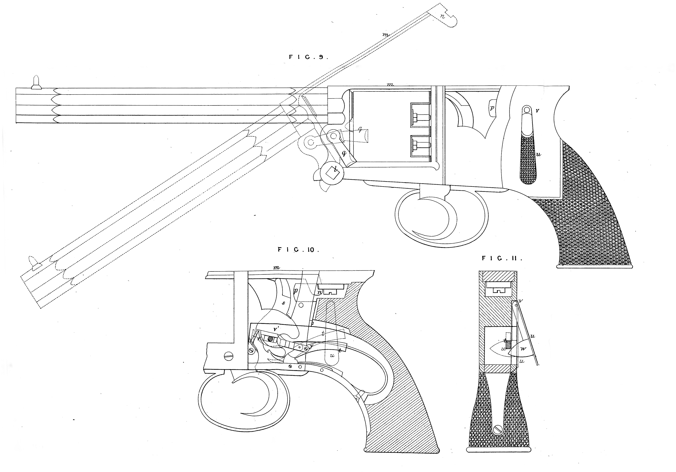
Fig. 4* represents a longitudinal section of another cartridge according to our Invention. This cartridge is in every respect like cartridges used with needle guns, with the exception that, instead of the point or needle by which the cap/, is fired belonging to the gun, it is placed in each individual cartridge as seen at <7, instead of the needle of the gun being projected into the cartridge, for that purpose*. In order to fire this cartridge the pin g is struck by a blunt striker (irf action similar to the ordinary needle) which drives the pin g9 into the cap and so discharges the cartridge; the butt of the cartridge and pin g of the discharged cartridge are thrust up the barrel and discharged at next shot. The pin g, being central, may be a little under the surface of the cartridge which requires no other adjustment in order that the striker may take proper effect. I sometimes form these cartridges with a case or lining of thin brass or other sheet metal as seen at y,y\ Fig 4*, which encircles the wad containing the cap, and extends throughout the length of the cartridge, the edges of the metal having a lap on itself equal to about a third or fourth part of the circumference, a capsule of thin metal may be used in the like manner. The third part of our Invention which relates to improvements in breech-loading guriS is represented in Figs. 5, 6, 7, & 8; Fig. 5, shows the breech part in longitudinal section of the gun known as Rissack's in which the barrel is mounted on a pin h, on which it moves as seen dotted, when the plug i is WitlidVawtf by its rapid pitch screw, actuated by the lever k, as well understood. Fig. 6 is an external view while Fig. 7 represents an end view of the plug i, and Fig. 8 a longitudinal section of plug i. Our improvements consists in'forming a recess xyx, in the nose of plug i, into which the base of fhd cartridge* is received. The nose of the plug i, is received within a recess ift the breech erfd of the barrel, and the recess xy is such that the mouth coincides With the bore of the barrel, behind which point it is contracted ami again enlarged even to a greater diameter than the bore of the gun. The cartridge when introduced at the breech and forced forward by the pressure of the nose of the plug i, meets with an obstruction from the contraction of the barrel, and is by such or other resistance caused to enter the chamber x, x. When the cartridge is fired the force of the explosion enlarges the base to fill the recess x, and this being undercut it becomes tightly fixed therein, the cartridge case covering the joint, and the force of the explosion on the cartridge and on the metal surrounding x, causes the joint to be tight. On withdrawing the plug i to reload, and on moving the barrel on its joint pin h9 for that purpose, the cartridge is drawn back-r wards and held tightly by $he breech plug and is thus removed without the necessity of picking it out with a hook as now practised. Fig. 8*, represents a portion of a gun in which the barrel slides, and is withdrawn from the breech, being an arrangement known as Bastin’s Patent; the breech plugs or nose pieces y, y, have recesses formed therein, and fit into the barrels in manner precisely similar to that before described, wjith reference to Figs. 5, 6, 7, & 8, being for like purpose ; the Drawing shows the cartridge dotted, in the position it would occupy when first introduced, and before closing the gun, as also the position occupied by the cartridge case after the gun is discharged, and the barrels opened. In this case, we fire the gun by the ordinary nipple and detonating cap, the fire from which passes by the channel from the nipple, which is carried through the breech at the centre of the bore; and in order that the fire may take effect, we form the cartridges with a hole in the centre of the end wad, through which the fire enters and ignites the powder. This method of withdrawing the cartridge case is also applicable to other arrangements of breech-loading guns, as will be readily understood without further illustration. Fig. 9, represents a side view of a revolver pistol constructed according to our Invention, and Fig. 10, a section showing part of the action of the same, and Fig, 11, a transverse section in further illustration of the same. The first part refers to using the barrel as a lever for loading; for this purpose we joint the barrel to the frame at Z, so that it will move thereon as on a hinge, as seen by the dotted lines, the upper tie bar m having a catch w, which is secured and released by a spring catch and thumb bolt p, which also serves for removing the revolving chamber, as well understood. To the bar supporting th® barrel, from the joint pin Z, we joint a short rammer q, by which we ram the charges in the small chambers of the revolving piece, using the barrel as a lever moving on fulcrum Z for that purpose. The next part refers to disposing the back part of the lock frame and stock of revolving chamber pistols, so that the line of resistance of the hand in firing is in a direct line with the line of recoil, as will be readily understood by reference to Fig. 9, without further description. Another part of our Invention consists of an arrangement of the trigger and lock of these pistols, in connection with a safety guard or lever, this is exhibited at Figs. 10 & 11 ; r is the pall of the trigger, giving motion to the hammer s, which may be raised a little by the action of the trigger, and held on half cock by catch lever t; by the continuance of the motion of the trigger, the hammer is raised to full cock, but it will not discharge without the safety guard being brought into play. This safety guard consists of a lever w, on which the thumb of the hand holding the pistol is placed, it is mounted on a fulcrum at v, and constantly pressed outwards from the stock by a suitable spring; w is an inclined surface projecting from lever u, which comes immediately under the tail of catch lever t; to the catch lever t a bar vl is jointed at y, the end of which bar abuts against the pall r, when the lock is at full cock. Thus when the lever u is pressed toward the stock, the incline w slides on and lifts the tail of catch lever £, thereby removing the catch of the half cock, and at same time (if the trigger has been previously completely pulled) throwing out the pall r from its hold on the cock, thereby producing the fall of the hammer, and consequently the discharge of the pistol. If on the other hand the safety guard has been acted on first, the mere effect of pulling the trigger will full cock and discharge the pistol immediately and without interruption, the click sliding from its hold of the cock by reason of the forward position of and contact with bar vl. The last part of our Invention, which relates to improvements in breech-loading guns, in which the action moves out of the line of the barrel, is represented at Figs. 12, 13, & 14, Fig. 12 being a side view of that part of the gun containing the action, & Figs. 13 & 14 the parts of the action detached ; d2 is the body part of the action, which is mounted on the joint pin on which the action moves out of the line of the barrel as usual; on the cylindrical part ft* of the body is fitted the cap or socket piece c* the end of which moves up and closes the breech end of the barrel. This piece c2 is fitted to slide on ft1, and has clutch pieces d\ d\ which interlock with like pieces e2, e2, on the body; when so interlocking, or in position to do so, the cap pieces c8 may be slid back from, and so as to disclose the breech of the barrel; on the other hand, when the parts d1 & abut end to end as seen dotted black in Fig. 13, the piece C1 is forced up against and closes the breech of the gun. The motions of the sliding cap are communicated to piece C1 by means of a short lever/1 passing through and pivotted to the cap, having at the short end a few teeth which take iuto rack teeth or notches cut in the body part of the action. The teeth cut in b2 are in part carried a quarter round, so that the cap piece c2 and with it the lever/1, are free to move round on the body 6* to the extent of a quarter revolution. In the position of the cap £*, shown red, it is free to slide & is slid backwards, so as to interlock parts d2 & the teeth 7, 7, in the body being continued at that point, so that the teeth on the short end of lever may by its action propel the cap in the direction required. The action is then free to be raised to the vertical position as indicated by dotted lines in Fig. 12, and the gun loaded. When the action is lowered, the cap is advanced by the motion of the lever f* to its forward position, so that the nose enters and closes the breech, it is then turned partially round, causing the parts d2 & c* to abut as shown black, which fixes the cap piece c2 firmly in its place, and the discharge may then take place, the abutting ends of parts d% & e\ may be slightly inclined so that the pressure of cap piece up to the breech may be increased by the movement of rotation. This system of breechloading guns being well known, the other parts of this gun will be readily understood without further description. Having described the nature of our Invention, and the manner of performing the same, we declare that what we claim as our Invention to be protected by the herein-before in part recited Letters Patent, is,— First, the peculiar combination and arrangement of the parts of a gun lescribed with reference to and represented in Figs. 1 & 2, of the Sheet of Orawings hereunto annexed. Secondly, constructing cartridges to be discharged by means of a wire struck by a projecting pin on the cock or hammer, which forces such wire within the limits of the cartridge, as and for the purposes and as herein-before described. Thirdly, constructing cartridges fired by the penetration of a needle or sharp point with such needles or points forming part of their construction as described. Fourthly, forming the cavity x in the nose of the plug or breech-piece of breech-loading fire-arms, for the purpose of closing the joint and withdrawing the cartridge as described. Fifthly, the application of the barrel of revolving pistols, to act as a lever on the rammer, in loading such pistol chamber as herein-before described. Sixthly, the arrangement or disposition of the lock, frame, and stock of evolving chamber pistols, as and for the purposes described & as represented. Seventhly, the application and arrangement of parts constituting the safety ward of revolving chamber pistols as herein-before described. And lastly, we claim the combination of parts constituting the action of breech-loading guns herein-before described and represented at Figs. 12, 13, & 14, of the Drawings, hereunto annexed. . In witness whereof, I, the said William Nicholas Norman, on behalf of myself and the said John Rigby, have hereunto set my hand and seal, this Sixth day of October, in the year of our Lord One thousand eight hundred and sixty. WM. N. NORMAN. (l.s.) Witness to the signature of Wm. N. Norman, John Pope.