
British 125
A.D. 1852 N° 125.
Fire-arms.
LETTERS PATENT to Thomas Hunt, of Leman Street, in the County of Middlesex, Gun Maker, for the Invention of “Improvements In Fire-Arms.”
Sealed the 12th January 1853, and dated the 1st October 1852.
PROVISIONAL SPECIFICATION left by the said Thomas Hunt at the Office of the Commissioners of Patents, with his Petition, on the 1st October 1852.
I, THOMAS HUNT, of Leman Street, in the County of Middlesex, Gun Maker, do hereby declare the nature of the said Invention for “Improvements In Fire-Arms” to be as follows:—
This Invention consist, first, of so arranging the lock and parts of a fire-arm having several barrels (called revolvers) that the several charges may be ignited in succession by the same needle.
Secondly, my Invention consists of giving motion to a needle or instrument (used in a fire-arm to ignite the charge) by means of a spring, the end of which moves along an incline, and the needle or instrument is brought back by a stronger spring acting on the trigger, and this movement also moves a tube to and fro, & so prevents the escape of gas.
Thirdly, the Invention consists of applying a disc, which is caused to revolve (and with it the barrels) by pulling the trigger, and at the same time the trigger puts in motion a bolt which locks the disc, and retains the barrel just previous to discharging.
SPECIFICATION in pursuance of the conditions of the Letters Patent, filed by the said Thomas Hunt in the Great Seal Patent Office on the 1st April 1853.
TO ALL TO WHOM THESE PRESENTS SHALL COME, I, THOMAS HUNT, of Leman Street, in the County of Middlesex, Gun Maker, send greeting.
WHEREAS Her most Excellent Majesty Queen Victoria, by Her Letters Patent, bearing date the First day of October, in the year of our Lord One thousand eight hundred and fifty-two, in the sixteenth year of Her reign, did, for Herself, Her heirs and successors, give and grant unto me, the said Thomas Hunt, Her special licence that I, the said Thomas Hunt, my executors, administrators, and assigns, or such others as I, the said Thomas Hunt, my executors, administrators, and assigns, should at any time agree with, and no others, from time to time and at all times thereafter during the term therein expressed, should and lawfully might make, use, exercise, and vend, within the United Kingdom of Great Britain and Ireland, the Channel Islands, and Isle of Man, an Invention for “IMPROVEMENTS IN FIRE-ARMS,” upon the condition (amongst others) that I, the said Thomas Hunt, by an instrument in writing under my hand and seal, should particularly describe and ascertain the nature of the said Invention, and in what manner the same was to be performed, and cause the same to be filed in the Great Seal Patent Office within six calendar months next and immediately after the date of the said Letters Patent.
NOW KNOW YE, that I, the said Thomas Hunt, do hereby declare the nature of the said Invention, and in what manner the same is to be performed, to be particularly described and ascertained in and by the following statement thereof (that is to say):
This Invention consists, first, of so arranging the lock and parts of a fire-arm having several barrels (called revolvers) that the several charges may be ignited in succession by the same needle.
Secondly, my Invention consists of giving motion to a needle or instrument (used in a fire-arm to ignite the charge) by means of a spring, the end of which moves along an incline, and the needle or instrument is brought back by a stronger spring acting on the trigger, and this movement also moves a tube to and fro, and so prevents the escape of gas.
And in order that my said Invention may be most fully understood, and readily carried into effect, I will proceed to describe the means pursued by me.
DESCRIPTION OF THE DRAWINGS.
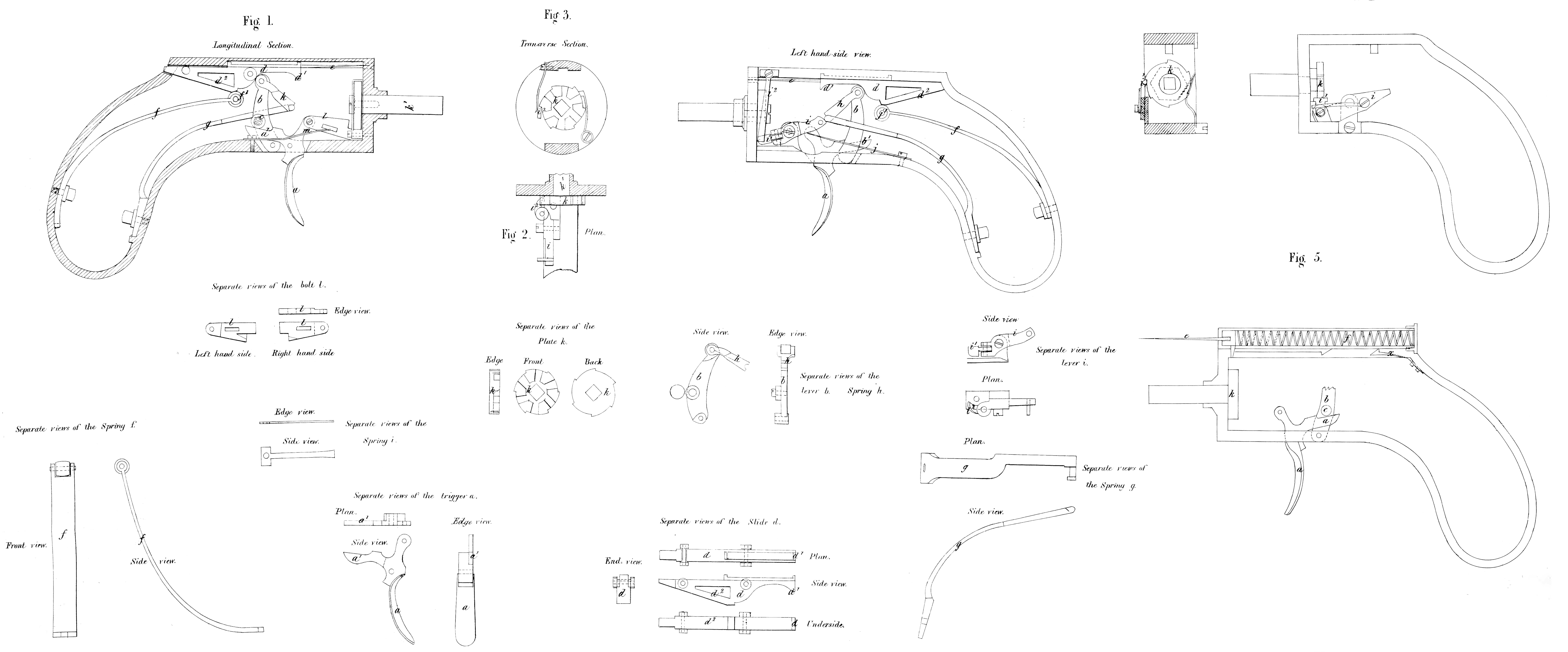
Figure 1, is a longitudinal section; Figure 2, is a plan in section of some of the parts; Figure 3, is a transverse section, and the remaining views in the Drawings show the parts separately. a, is the trigger, which gives motion to a lever b, by the part a^1, coming against the roller c, moving on an axis fixed to the lever b. The upper end of the lever b, moves in the curved portion of the sliding bolt d, which actuates the needle e, and causes it to enter the breeches of the barrels-in succession. The lever b, when it comes against the fore end d^1, of he bolt d , moves it a short distance, by which the roller f^1, on the spring f, will come on to the incline d^2, at the back end of the sliding bolt d , and the pressure of the spring f, will, then force forward the bolt d, and cause the needle to ignite the properly prepared cartridge within the barrel, which is for the time being in position; before the trigger, however, sets the sliding bolt d, free, to be acted on by its spring f, as above explained, it causes the barrels to revolve, so as to bring up a charged one into position to have its charge ignited by the needle or other instrument e, penetrating or striking the percussion cap or the cartridge.
In place of using the spring f, to force forward the needle, a spiral spring may be used, as shewn at Figure 5, where the incline is dispensed with, and a spring x, is caused to retain the coiled spring till the barrels have been turned, as herein described, and then the movement of the trigger touches the sliding bolt, and overcomes the cocking spring x.
The rotating of the barrels is accomplished in the following manner: g, is a strong spring, which is connected to the lever b, by the link h, which spring has constantly a tendency to bring back the trigger, and also the lever b, and by the lever b, to bring back the sliding bolt d, and this spring g, will do so, notwithstanding the spring f, immediately the trigger is released after discharging a barre). The end of the spring y, is constantly in contact with the lever i, that lover being constantly borne up by a spring j, as shown; the other end of the lever is formed with a moveable end i^1, suitably formed for entering the notches, and of being pressed thereto by the spring i^2, as shown; hence when the back end of the lever i, is pressed down, the moveable end enters a notch in the plate k, on the rotating axis k^1 which passes thro’ the revolving chambers, the disc 1, being within the body or frame, & is unattached to the barrel, and will rotate a distance suitable for bringing up one that is charged. And in order to insure this being done correctly, the bolt I, is used, which is attached to the upper part of the trigger by a pin joint, and the bolt I, is constantly borne down by a spring in, as shown; hence when the trigger is pulled it will first cause the barrels to rotate, and they will next be locked correctly in position by the bolt l, when the spring f, will come into action and move the needle or instrument C, which is to ignite the charge. And immediately on releasing the trigger the spring g, will restore all parts into position, to admit of the trigger being again pulled to bring up and discharge another barrel.
Having thus described the nature of my said Invention, and the
manner of performing the same, I would have it understood that I do not claim the parts separately, but only the manner of combining them.
In witness whereof, I, the said Thomas Hunt, have hereunto set my hand and seal, this First day of April, in the year of our Lord One thousand eight hundred and fifty-three.
THO. HUNT. (L.S)
Witness,
Fred^K Harris.