
British 69
A.D. 1852 N° 69
Repeating Pistols and Rifles.
LETTERS PATENT to William Moore, of Birmingham, in the County of Warwick, Gun Maker, and William Harris, of Birmingham, aforesaid, Gun Maker, for the Invention of “An IMPROVEMENT IN REPEATING PISTOLS AND RIFLES.”
Sealed the 30th March 1853, and dated the 1st October 1852.
PROVISIONAL SPECIFICATION left by the said William Moore and William Harris at the Office of the Commissioners of Patents, with their Petition, on the 1st October 1852.
We, William Moore & William Harris, do hereby declare the nature of the said Invention for “AN IMPROVEMENT IN REPEATING PISTOLS AND RIFLES” to be as follows:—
Our Invention consists in the introduction of a hinge or other joint in the frame of repeating pistols or rifles, in which the revolving barrel works; that is to say, the single barrel, along which the projectile is urged by the explosion of the powder in one of the barrels of the revolving chamber, instead of being fixed to the frame in which the said chamber revolves, is connected therewith by a joint, so that the said single barrel may be turned upon the said joint from its place in front of the said revolving chamber.
The said joint may be in the upper or lower, or any other convenient part of the said frame.
SPECIFICATION in pursuance of the conditions of the Letters Patent, filed by the said William Moore and William Harris in the Great Seal Patent Office, on the 31st March 1853.
TO ALL TO WHOM THESE PRESENTS SHALL COME, we, William Moore, of Birmingham, in the County of Warwick, Gun Maker, and WILLIAM HARRIS, of Birmingham, aforesaid, Gun Maker, send greeting.
WHEREAS Her most Excellent Majesty Queen Victoria, by Her Letters Patent, bearing date the First day of October, in the year of Lord One thousand eight hundred and fifty-two, in the sixteenth year of Her reign, did, for Herself, Her heirs and successors, give and grant unto us, the said William Moore and William Harris, Her special licence, that we, the said William Moore and William Harris, our executors, administrators, and assigns, or such others as we, the said William Moore and William Harris, our executors, administrators, and assigns, should at any time agree with, and no others, from time to time and at all times thereafter during the term therein expressed, should and lawfully might make, use, exercise, and vend, within the United Kingdom of Great Britain and Ireland, the Channel Islands, and Isle of Man, an Invention for “An Improvement In Repeating Pistols And Rifles,” upon the condition (amongst others) that we, the said William Moore and William Harris, or one of us, by an instrument in writing under our hands and seals, or under the hand and seal of one of us, should particularly describe and ascertain the nature of the said Invention, and in what manner the same was to be performed, and cause the same to be filed in the Great Seal Patent Office within six calendar months next and immediately after the date of the said Letters Patent.
NOW KNOW YE, that we, the said William Moore and William Harris, do hereby declare the nature of the said Invention, and in what manner the same is to be performed, to be particularly described and ascertained in and by the following statement thereof (that is to say):
Our Invention consists in constructing the frame in which the chambers of repeating pistols and rifles work with a joint, so that the barrel, along which the projectile is urged after leaving the revolving chamber, may be readily removed from the front of the said revolving chamber, so as to give facility in loading the said chamber; and by which said method of construction we also obtain the advantage of being able to connect the said barrel with the said revolving chamber during the discharge of the pistol or rifle, as herein-after particularly explained.
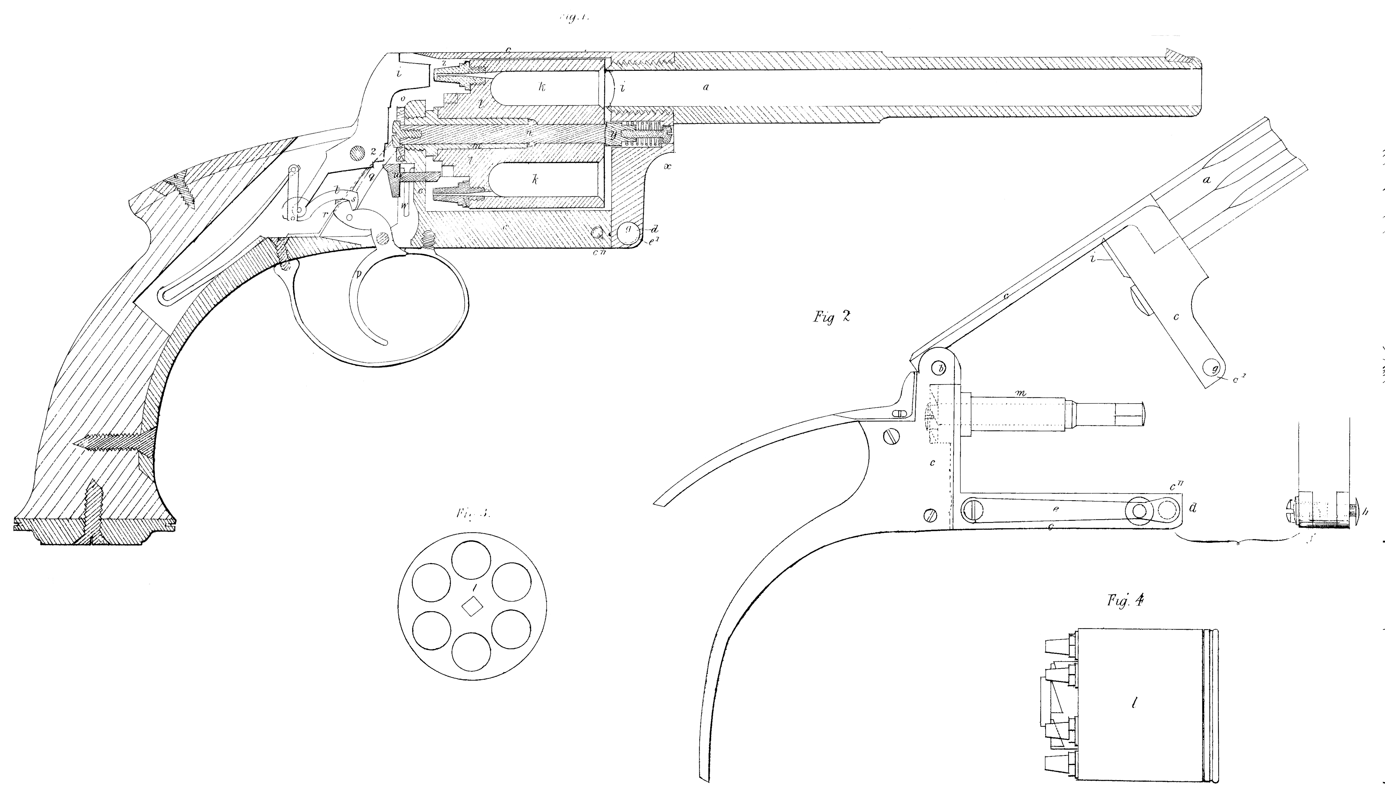
Figure 1, of the accompanying Drawing represents in vertical section
a pistol made according to our Invention; and Figures 2, 3, and 4, represent portions of the same. a, Figures 1, and 2, is the barrel, which is connected with the body of the pistol by the joint b, in the frame C. In Figure 1, the said frame, is represented closed; in Figure 2, the said frame is represented partly open by the disengagement of the fastening at d, and the raising of the barrel a, upon the joint b. The said joint b, may be made in any convenient manner; but we find an ordinary hinge joint, from the middle of which a portion has been cut away to admit of the action of the hammer, as seen in Figure 1, answer very well. On bringing the barrel a, into its place, the ends c^1, c^11, of the frame become connected together by the fastening represented, and which is made as follows:— e, is a spring, which bears against the side of the frame c; the said spring e, carries a stud f, having an inclined face, as shewn in dotted lines in the front view (see Figure 2). When the vertical side of the frame is brought down into its place, the end thereof presses back the said pin f, out of the frame, until the hole g, is opposed to the said pin f, when the said pin is forced into the said hole by the said spring e, and the fastening effected. By pressing on the button h, the pin f, is disengaged from the hole g, while the barrel a, and vertical side of the frame are raised. i, is a conical annular projection on the end of the barrel a, which is made accurately to fit the funnel shaped mouths of the detonating barrels k, k, of the chamber l, and against which projection the said mouths of the detonating barrels are forced at the moment of discharge in the following manner:— m, is a hollow fixed axis, on which the chamber l, rotates; the said chamber l, is keyed to the axis n, by a sliding key; the said axis n, passes through the fixed hollow axis n, into the interior of the lock, and carries on its end the disco, on the face of which a series of ratchet teeth are made; by pressing the trigger p, the arm or lever q, which is pressed against the face of the said ratchet by the spring r, engages with one of the teeth of the said ratchet, and moves the said chamber through one sixth part of a revolution, by which a detonating barrel k, is brought opposite the barrel a. The continued motion of the trigger brings the shoulder s, of the link t, against the end of the slide u, and forces the said slide against the posterior face of the chamber l, so as to cause it to slide on the hollow axis m, and axis n, and bring the funnel shaped mouth of the barrel k, to bear against the conical mouth i, of the barrel a, and thus, during the explosion, to constitute the two barrels one continuous. barrel. When the trigger has been moved to its full extent by the pressure of the finger, the shoulder s, of the link t, escapes from the shoulder v, of the trigger, and the hammer falls; but the slide u, is kept in its place by the pressure of the said shoulder v, of the trigger, which comes in contact with it at the moment when the shoulder s, of the link t, escapes from it.
When the hammer is again raised, the slide u, is forced back by the spring w, and the chamber l, is forced back, so as to disconnect itself from the barrel a, by the coiled spring x, forcing the plug y, against the anterior face of the chamber l. The posterior face of the chamber l, is formed into a series of inclined planes (see Figure 4), so that when the slide u, is pressed forwards, the said face, bearing against the end of the said slide, causes the said chamber to advance as it rotates, and gradually to bring the funnel shaped mouth of the detonating barrel close against, and at the proper moment force it into contact with, the projecting end of the barrel a.
By pulling the trigger to any extent short of what is necessary to discharge the pistol, and afterwards removing the finger from the said trigger, the cock or hammer is raised from the nipple z, and locked in that position until it is liberated by the further action of the finger on the trigger. The said locking of the hammer 1, is thus effected:— By partially raising the said hammer 1, the slide u, urged by the spring w, escapes from the shoulder 2, against which it previously pressed, and being shot by the spring w, under the said shoulder, the hammer can no longer fall to its full extent; the under part of the shoulder 2, bearing upon the top of the slide u. When, however, the trigger p, is pulled so far that the hammer becomes detached from it, in the manner already described, the slide is at that time pressed against the chamber 1, by the shoulder v, of the trigger, so that when the hammer falls, the slide U, on the finger being removed from the trigger, bears against the vertical face of the shoulder 2, of the hammer; and it is only after the hammer has been partially raised, that the slide u, assumes the position represented, by escaping underneath the said shoulder 2.
The advantages of our method of construction further consist of the completeness of the frame when closed, and the facility with which it can be opened to load the chambers or remove them; and also the facilities of manufacture which it affords; for, by the said arrangement, the moving parts in the body of the pistol can be more readily put together than when all the sides of the frame are made in one piece with the barrel; and when the said frame and barrel are in one piece, a defect in the barrel or frame may render the whole pistol useless; whereas, by our arrangement, a defective barrel may be replaced by a new one.
Another advantage of our method of constructing the frame is, that its front side has no connection with the axle or centre pin on which the chambers revolve; the cylinder containing the said axle being screwed into the back portion of the frame (or body of the pistol); and a frame so constructed can be better made to admit of the chambers advancing to interlock the concave mouth of each chamber with the fore barrel at the time of explosion.
The only precaution necessary, in opening the frame, for safely loading, is that of first placing the pistol at half cock, which is done by a partial pull of the trigger, or by placing the thumb upon the cock, in the usual manner of cocking.
Another advantage is, that the front vertical portion of the frame and the barrel may be made of twisted iron proper for barrels, while the body may be case-hardened, whereby it resists rust much better, and is, from its hardness, better for the action of the moving parts.
The barrel may, as heretofore, be either screwed into or on the front portion of the frame, or the front side of the frame may be made of the same piece of iron or steel as the barrel.
Having now described the nature of our said Invention, and the manner of carrying the same into effect, we wish it to be understood that we do not limit ourselves to the precise method of carrying our Invention into effect herein described, as the same may be varied without departing from the nature of our said Invention.
But we claim the construction of a hinge joint frame for containing the chamber of repeating pistols and rifles, whether the said hinge joint be situated in that part of the said frame herein described or in any other part of the said frame, whereby the several advantages herein described as arising from the said hinge joint frame may be realized.
In witness whereof, we, the said William Moore and William Harris, have hereunto set our hands and seals, this Twenty ninth day of March, in the year of our Lord One thousand eight hundred and fifty-three.
WILLIAM MOORE. (L.S.)
WILLIAM HARRIS. (L.S.)
Witness, George Shaw.