
Britain 370
LETTERS PATENT to William Edward Newton, of the Office for Patents, 66, Chancery Lane, in the County of Middlesex, Civil Engineer, for the Invention of “IMPROVEMENTS IN THE CONSTRUCTION OF FIRE-ARMS.” — A communication.
Sealed the 5th August 1856, and dated the 13th February 1856.
PROVISIONAL SPECIFICATION left by the said William Edward Newton at the Office of the Commissioners of Patents, with his Petition, on the 13th February 1856.
I, William Edward Newton, of the Office for Patents, 66, Chancery Lane, 5 in the County of Middlesex, Civil Engineer, do hereby declare the nature of the said Invention for “IMPROVEMENTS IN THE CONSTRUCTION OF FIRE-ARMS,” to be as follows:—
In the efforts heretofore made to apply the repeating principle to that class of arms which are fired from the shoulder, it has thus far not been found practicable to avoid the danger, to which all of them are more or less liable, of premature explosion, either of the magazine containing the powder for the successive charges, or of the chambers contiguous to the one discharged, by which serious accidents have occurred to those making use of them, resulting in loss of limb and life. To avoid entirely this danger, and to make the musket or the rifle, when constructed upon the repeating principle, as safe to those discharging them as the repeating pistol, is the object of the present Invention, which consists in bringing up the chambers separately and successively into a line with the gun barrel, while all the others remain in a vertical position, each one at the instant of its discharge being so far removed from the others as to avoid the possibility of communicating combustion from one tube to another.
Another improvement consists in closing the joint between the barrel and the charge chamber by means of a sliding ring, which is made to cover the joint at the instant of the discharge, and is moved forward out of the way of the charge chamber whenever it becomes necessary to bring up a new chamber into line with the barrel. The discharge of the piece is prevented by means of a lever, which keeps the hammer from falling whenever the joint between the barrel and the charge chamber is not closed by the sliding ring, and the movements of the sliding ring are effected at the moment required by means of mechanism acting in concert with the moving parts of the lock. The charges are inserted in a series of chambers, which are attached by a pivot or hinge to a revolving plate, from which they bang in a vertical position, until by the revolution of the plate they are elevated, and brought in succession one at a time into a line with the barrel, in a position to be discharged. After a tube is discharged, it is lowered by the revolution of the plate to its original position, at the same instant that the next in order is brought up in a line with the barrel, and so on through the whole series until all the chambers are discharged, when they may be removed for the purpose of reloading; or where a great number of discharges are required in immediate succession, as in action upon a field of battle, the set of discharged chambers may be replaced by another set, one or more sets of chambers being carried about the person for a the purpose.
SPECIFICATION in pursuance of the conditions of the Letters Patent, filed by the said William Edward Newton in the Great Seal Patent Office on the 13th August 1856.
TO ALL TO WHOM THESE PRESENTS SHALL COME, I, WILLIAM EDWARD Newton, of the Office for Patents, 66, Chancery Lane, in the County of Middlesex, Civil Engineer, send greeting.
WHEREAS Her most Excellent Majesty Queen Victoria, by Her Letters Patent, bearing date the 13th day of February, in the year of our Lord 1856, in the nineteenth year of Her reign, did, for Herself, Her heirs and successors, give and grant unto me, the said William Edward Newton, Her special license, that I, the said William Edward Newton, my executors, administrators, and assigns, or such others as I, the said William Edward Newton, my executors, administrators, and assigns, should at any time agree with, and no others, from time to time and at all times thereafter during the term therein expressed, should and lawfully might make, use, exercise, and vend, within the United Kingdom of Great Britain and Ireland, the Channel Islands, and Isle of Man, an Invention for “IMPROVEMENTS IN THE CONSTRUCTION OF FIRE-ARMS,” being a communication from abroad, upon the condition (amongst others) that I, the said William Edward Newton, by an instrument in writing under my hand and seal, should particularly describe and ascertain the nature of the said Invention, and in what manner the same was to be performed, and cause the same to be filed in the Great Seal Patent Office within six calender months next and immediately after the date of the said Letters Patent.
NOW KNOW YE, that I, the said William Edward Newton, do hereby declare the nature of the said Invention, and in what manner the same is to be performed, to be particularly described and ascertained in and by the 20 following statement, reference being had to the Drawing hereunto annexed, and to the letters and figures marked thereon (that is to say):—
In the efforts heretofore made to apply the repeating principle to that class of arms which are fired from the shoulder, it has thus far not been found practicable to avoid the danger to which all of them are more or less liable of premature explosion, either of the magazine containing the powder for the successive charges, or of the chambers contiguous to the one discharged, by which serious accidents have occurred to those making use of them, resulting in loss of limb and life. To avoid entirely this danger, and to make the musket or the rifle, when constructed upon the repeating principle, as safe to those discharging them as the repeating pistol, is the object of the present Invention, which consists in bringing up the chambers separately and successively into a line with the gun barrel, while all the others remain in a vertical position, each one at the instant of its discharge being so far removed from the others as to avoid the possibility of communicating combustion from one tube to another.
The 2nd part of this Invention consists in closing the joint between the barrel and the charge chamber, by means of a sliding ring, which is made to cover the joint at the instant of the discharge, and is moved forward out of the way of the charge chamber whenever it becomes necessary to bring up a new chamber into line with the barrel.
The 3rd part of this Invention consists in an improved method of preventing the discharge of the piece whenever the joint between the barrel and the charge chamber is not closed by the sliding ring.
The 4th part of this Invention consists in a combination of parts whereby the exact movements of the sliding ring are effected at the moment required, as will be hereafter more fully explained.
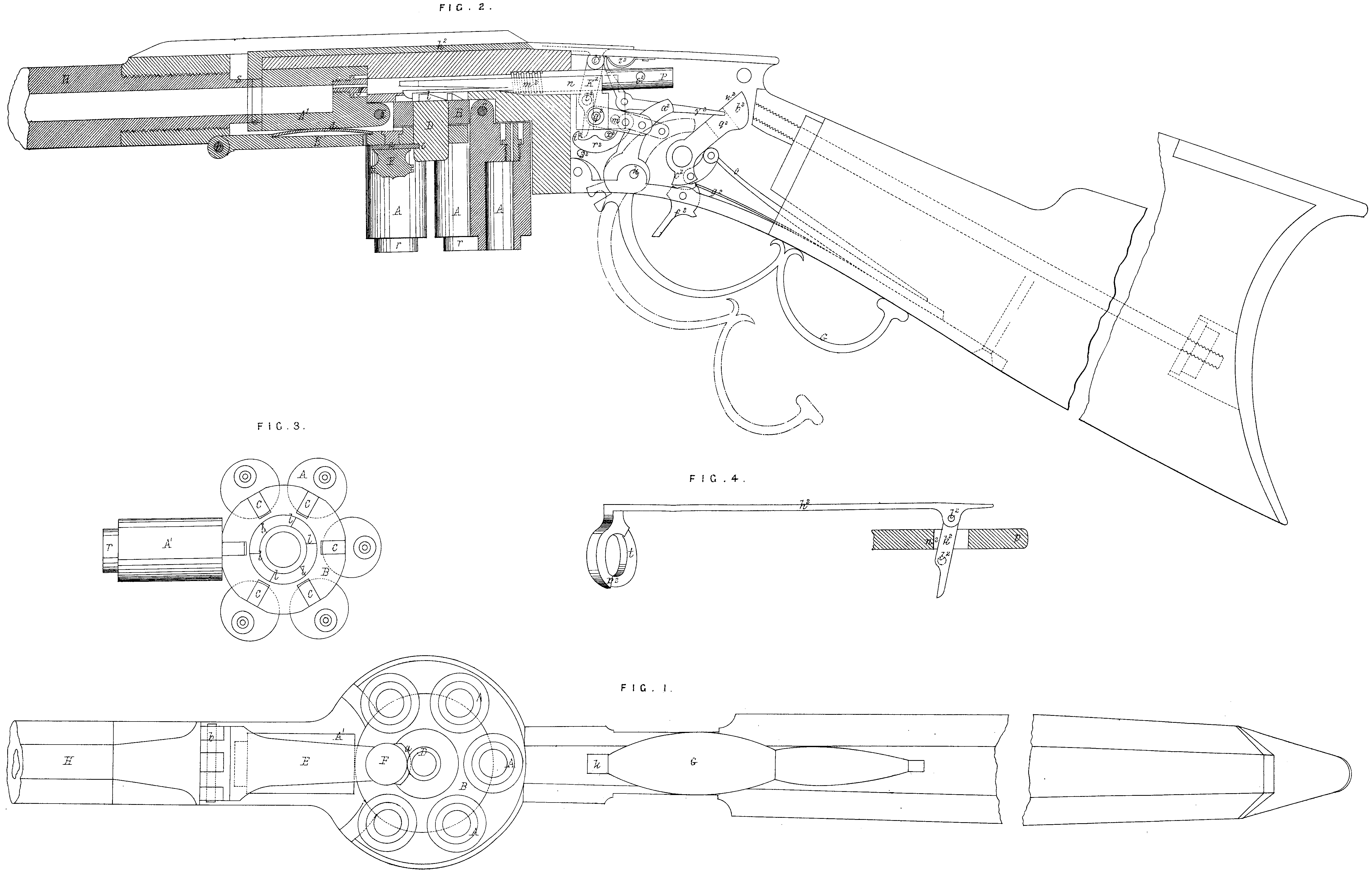
In the accompanying Drawing, Fig. 1 is a view from beneath, of a rifle with the improvements attached; Fig. 2, a vertical section through the centre of the same; Fig. 3, a detached view of the chambers, showing the manner in which they are hinged to the revolving plate which carries them; Fig. 4, detail, which will be referred to hereafter.
The charges are inserted in a series of chambers, which are attached by a pivot or hinge to a revolving plate, from which they hang in a vertical position, until by the revolution of the plate they are elevated, and brought in succession, one at a time, into a line with the barrel, in a position to be discharged. After a tube is discharged, it is lowered by the revolution of the plate to its original position, at the same instant that the next in order is brought up in line with the barrel, and so on through the whole series until all the chambers are discharged, when they may be removed for the purpose of reloading; or where a great number of discharges are required in immediate succession, as in action upon a field of battle, the set of discharged chambers may be replaced by another set, one or more sets of chambers being carried about the person for the purpose.
A, in the Drawings, represents the chambers, which are hinged to the plate B at C, and which may be turned up into a horizontal position, as seen at A^1 in all the Figures. The plate B is adapted to and revolves upon the pin D, which projects downwards from the body of the gun; this plate with its charge chambers is held in position by a button or catch a upon the end of the lever E; this button is operated by the knob F, and enters a notch in the pin D, as seen in Fig. 2 at c. The lever E is pivoted at b, and when in place, as seen in Figs. 1 and 2, serves to throw up the chambers one by one as the plate B is revolved, the spring d holding them up against a firm bearing above until they are securely locked with the barrel, as will be hereafter explained. When the plate B with its chambers is to be removed from the gun, the catch a is turned and the lever E depressed, which leaves the plate B with its charge chambers free to be separated from the gun. The chambers are revolved and raised into line with the barrel in the following manner:— G is the “guard,” which in lieu of being attached permanently to the gun is pivoted at k, as seen in Fig. 2; the short arm of this lever is connected by means of the link m with the slide n; this slide n carries a spring dog p, which engages with the teeth 1, projecting from the upper side of the plate B. As now the guard is thrown forward into the position represented in red in Fig. 2, the dog p engages with one of the teeth 1 (the number of which corresponds to that of the charge chambers), and revolves the plate sufficiently to bring the next succeeding chamber into line with the barrel; this is effected by the lever E, against which the chamber A strikes as it revolves, and by which the latter is thrown up into the position represented in Figs. 1 and 2 in line with the barrel and rearly to be discharged. The charge chamber is secured to the barrel of the gun at the instant of the discharge, and a tight joint between the two insured in the following manner:— The forward end of each chamber is turned down, as seen at r, the rear end of 15 the barrel H being furnished with a corresponding offset s; upon this latter is fitted a ring t, which previous to the discharge is made to pass over the joint between the chamber and the barrel, in a manner which will be hereafter explained. The piece is cocked and discharged in the following manner:— As the guard G is depressed, for the purpose of rotating the charge chambers, its short arm a^2 strikes against the hammer b^2, and throws it back, until the point c^2 catches over a shoulder upon the trigger f^2, as seen in Fig. 2; the hammer is thus retained cocked until the trigger is pulled, so as to release the hammer, when the latter is thrown by its spring O against the hammer rod P, the opposite end of which is projected against the nipple 9 (Fig. 2), for the purpose of exploding the cap and discharging the piece. Whenever the piece is not cocked, the trigger is thrown up and concealed from view by its spring g^2. The ring t, which covers and closes the joint between the charge chamber and the barrel, is operated as follows:— It is attached to the rod h^3, to which is hinged at i^2 the arm k^2, which is pivoted to the lock plate at 12. This arm passes through a slot in the hammer rod P, so formed, that when the hammer rod is projected by the blow of the hammer it shall advance without moving the arm k^3; but when the hammer rod is relieved of the pressure of the hammer, it is thrown back by the spring m^2, until the shoulder n^2 of the slot rests against the arm k^3. When the guard G is depressed and the slide n is drawn back, the latter strikes against the pin o^2, projecting from the hammer rod, by which the latter is drawn back slightly, by which means the shoulder p^2 upon the ring t is caused to arrest the motion of the charge chamber at the instant when it is in line with the barrel. The ring t is drawn over the joint between the chamber and the barrel by the return of the guard to its place, as follows:— q^2is a pin projecting from the slide n, which strikes against the lever k^3, and thus draws back the ring as required. The following device is employed for the purpose of throwing forward the ring from off the charge chamber before the latter is moved: r^3 is a hooked dog, which is pivoted to the link m, and is thrown forward as the guard is returned to its place, being held up by the pin s^2, as seen in Fig. 2, so that its hook t^2 shall catch the end of the arm k^2 when the guard first commences to move, by which means the arm k^3 is moved upon its fulcrum l^2, and, through the connections already explained, the ring t is thrown forward, and the chamber A^1 is left free to be moved by the continued motion of the guard. So soon as the ring is thrown sufficiently far forward to release the chamber, the dog r^3 is thrown off the lever k^2 by the the pin x^2 the pins s^2 and x^3 project sufficiently far from the lock plate to operate the dog. In order to prevent the piece from being discharged until the joint between the charge chamber and the barrel is covered by the ring t, the following device is employed: y^2 is a bent lever pivoted to the lock plate, one end of which is borne up against the arm k^2 by the spring z^2, the other end entering a mortice or slot q^2 through the hammer; when the ring t is thrown forward, the long arm of the lever y^2 is raised out of the slot q^2, so as to rest against the shoulder w^2 of the hammer, by which the latter is prevented from being thrown forward. When, however, the guard G is brought home to its place, and the ring t has covered the joint between the chamber and the barrel, the end of the lever y^3 is depressed, so as to enter the slot q^2 in the hammer, and the latter is left free to fall.
Having now set forth the nature of this Invention, and explained the manner of carrying the same into effect, I wish it to be understood that under the above recited Letters Patent I claim, bringing the tubes or short barrels in which the charges are placed separately and successively into a horizontal position, so as to form a continuation of the gun barrel, while the others retain a vertical position, as set forth for the purpose specified.
2nd, the ring t, operating in the manner substantially as herein described, for the purpose of closing the joint between the barrel and charge chamber at the instant of discharge, as set forth.
3rd, the lever y^2, in combination with the slot through the hammer, and with the ring t, for the purpose of preventing the discharge of the piece at all times when the joint between the barrel and charge chamber is not closed by its ring.
4th, the combination and arrangement of the parts by which the ring t is operated, as set forth.
In witness whereof, I, the said William Edward Newton, have hereunto set my hand and seal, the Eleventh day of August, in the year of our Lord One thousand eight hundred and fifty-six.
(L.S.) W. E. NEWTON.
Witness,
J. W. MOFFATT,
66 , Chancery Lane,