
US 50232
UNITED STATES PATENT OFFICE.
WM. H. ELLIOT, OF ILION, NEW YORK.
IMPROVEMENT IN REVOLVING FIRE-ARMS.
Specification forming part of Letters Patent No. 50,232, dated October 3, 1865.
To all whom it may concern:
Be it known that I, W. H. Elliot, of Ilion, county of Herkimer, and State of New York, have invented a new and Improved Method of Firing Repeating-Arms; and I do hereby declare that the following is a full and exact description thereof, reference being had to the accompanying drawings, and to the letters of reference marked thereon.
Similar letters of reference indicate the same devices in all the figures.
To enable others skilled in the art to comprehend, make, and use my invention, I will proceed to describe its nature, construction, and operation.
The nature of my invention consists in the employment, in a many-barreled arm, of a firing point for each chamber, so arranged and operating in relation to the hammer that one only of the points is driven forward at a time, and that each firing-point in its turn is driven forward, so as to fire the charges in regular order.
It also consists in the employment of cams in combination with several stationary firing-points or pins for throwing one of said pins after the others before the hammer, so as to fire the several charges in regular order; and it further consists in the employment of curved or angular firing-pins in combination with a reflecting-surface in the breech of the arm, for the purpose of changing the direction of the force of the hammer.
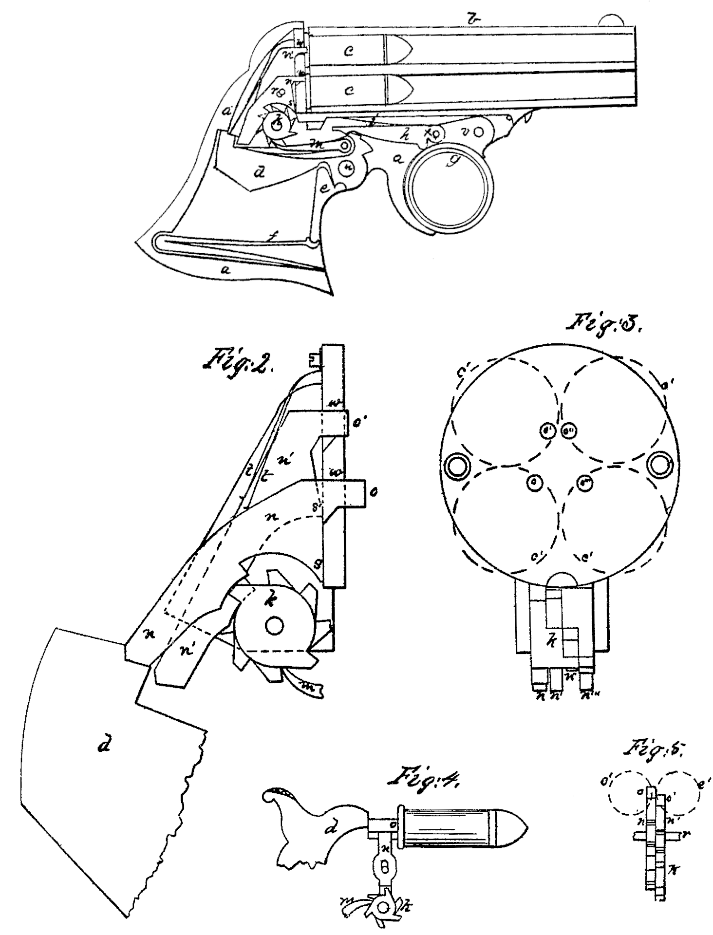
Figure 1 is a vertical section of the frame, barrel, and hammer of my improved pistol, showing the other parts in elevation. Fig. 2 is a magnified section of the breech-plate, showing the firing-pins and cam in elevation. Fig. 3 is a magnified front elevation of the breech plate, firing-pins, and cam. Fig. 4 is a modification of the same invention, showing the firing-pins and cam in elevation. Fig. 5 is a front elevation of the same.
a is the frame; b, barrel; c, cartridges in the chambers; c, position of the cartridges in relation to the breech-plate and firing-points; d, hammer; c, stirrup; f, mainspring; g, trigger; h, cocking-pawl; i, spring of the same; k, cams; m, revolving pawl pivoted to the hammer; n n’ n” n”‘, firing-pins; o o’ o” o”‘, firing-points, making a part of said pins; r, pin for fastening the firing-pins to the breech plate or frame of the pistol; s and s’, fulcrums upon which the pins turn as they fall off the can; t, springs of the firing-pins; u, hammer pin;v, trigger-pin; x, cocking-pawl pin; w and w’, reflecting-surfaces in the breech-plate, upon which the firing-pins glide, by which means the direction of the force of the hammer is changed from an upper to a horizontal direction.
My invention relates to that kind of arm in which many stationary barrels are employed, and is equally applicable to rifles and shotguns as to pistols; and the object of the invention is to dispense with moving the firing-points from one charge or chamber to the other by providing a firing-point for each chamber.
The operation of my improved arm is as follows: When the trigger is pushed forward preparatory to firing, the point of the cocking-pawl falls into the notch upon the hammer, and when the trigger is drawn back the hammer is raised until the under side of the cocking-pawl strikes the ring of the trigger, which raises the point of said pawl out of the notch and the hammer falls upon one of the pins. As the hammer is raised in the act of firing, the revolving-pawl, which is pivoted to the hammer, catches upon one of the projections of the cam, causing it to revolve under the firing-pins. By each motion of the hammer a new projection is brought under the firing pins, which throws one of them before the hammer, and as the hammer falls that pin is driven forward against the charge, as seen at n, Fig. 2. By the next motion of the hammer the cam is moved, another notch bringing another projection of the cam against another firing-pin, raising it so that the hammer can strike it, while the first pin is allowed by the cam to fall out of the reach of the hammer, as seen at Fig. 1, and so on till all the pins in their turn have been driven forward by the hammer.
By the employment of a firing pin or point for each chamber, and throwing them before the hammer, as herein represented, the motions of the several parts of the arm are simpler than they are when one revolving point is employed for several chambers, as in the former case the motions of every piece in the arm is in the same plane. As the firing-pins are driven upward by the hammer they strike against the upper side of the holes in the breech-plate and then shoot forward horizontally against the charge.
Figs. 4 and 5 represent a modification of my invention. In this case the firing-pins are moved up and down before the hammer, and are so constructed that when raised the hammer strikes them, but when down the hammer strikes over them without touching them.
In a many-chambered sporting-arm this invention would be particularly applicable. In this case the firing-pins should be located in the wrist of the arm in a horizontal position,the hammer striking their rear ends, the firing-points on their forward ends. When left to themselves the hammer would strike under them; but upon one of them being depressed, that one would be driven forward against the charge. Each of these firing-pins should be provided with a small thumb-piece projecting up through the wrist of the arm, so that by placing the thumb upon any one of them and depressing it the charge before that one would be fired.
Having described my invention, what I claim, and desire to have secured to me by Letters Patent of the United States, is—
1. In a many-barreled arm in which a separate firing point or pin is employed for each chamber, so constructing and operating said pins in relation to the hammer that only one of them will be driven forward at a time, as herein shown.
2. The combination of the cam and firing pins for the purpose of throwing one of said pins after the other before the hammer, as herein set forth.
3. The angular pins n, in combination with the reflecting-surface w, for the purposes herein set forth.
W. H. ELLIOT.
Witnesses:
Thos. Richardson,
J. Quackenbush.