
US 51117
UNITED STATES PATENT OFFICE.
WILLIAM MASON, OF ILION, NEW YORK, ASSIGNOR TO E. REMINGTON & SONS, OF SAME PLACE.
IMPROVEMENT IN REVOLVING FIRE-ARMS.
Specification forming part of Letters Patent No. 51,117, dated November 21, 1865.
To all whom it may concern:
Be it known that I, William Mason, of Ilion, in the county of Herkimer and State of New York, have invented certain new and useful Improvements in Breech-Loading Fire-Arms; and I do hereby declare the following to be a full, clear, and exact description of the same, reference being had to the accompanying drawings, making a part of this specification, in which—
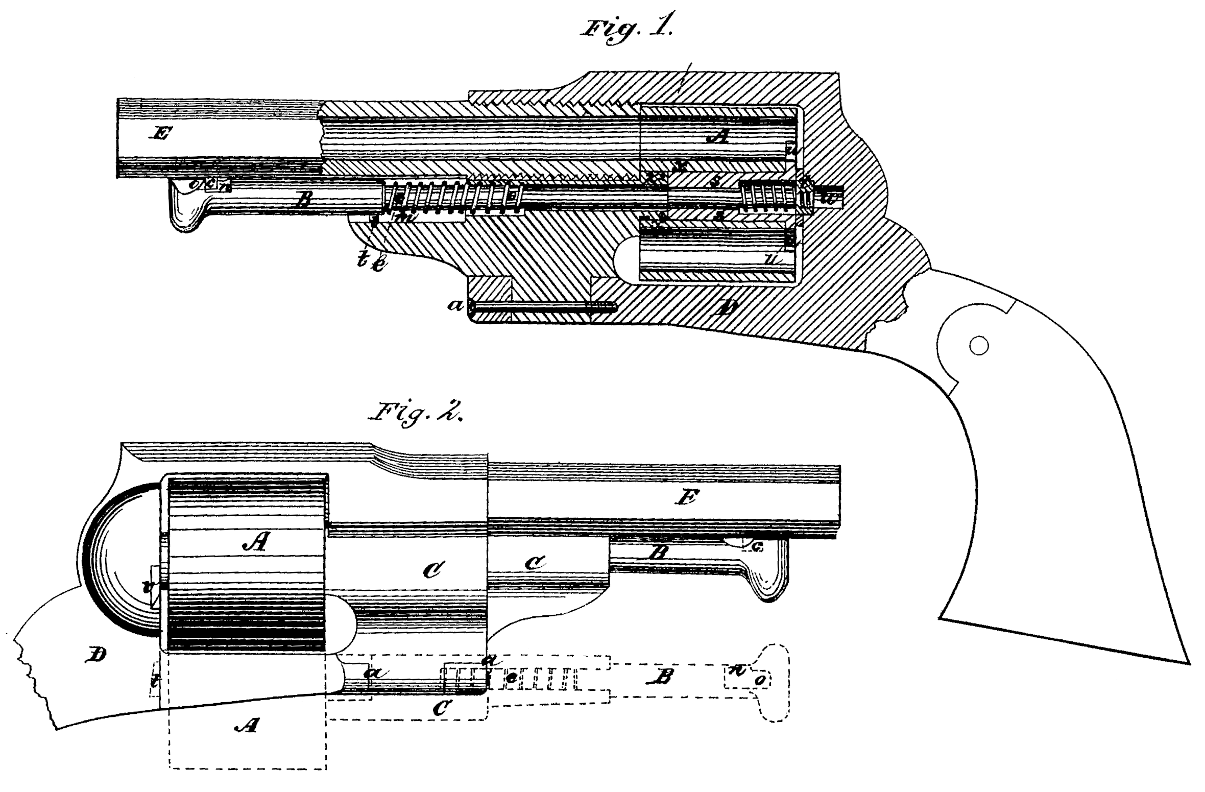
Figure 1 represents a side view, partially in section, to show the interior arrangement, otherwise concealed. Fig. 2 represents am external side view, and showing in red lines the position of the cylinder, pin, and portion of the frame when thrown out laterally to eject the empty cases for to reload the arm.
Similar letters of reference, where they occur in the separate figures, denote like parts of the arm in both of the drawings.
My invention consists, first, in swinging the revolving cylinder, with its base-pin, out of line of the center of the barrel and frame, when said cylinder is wholly supported when thus swung out at its fore end.
My invention further consists in the use of a concentric internal groove within and near the fore end of the cylinder, in connection with the concentric external groove and eccentric head on the rear end of the swinging support, said groove and head being fitted together and held in proper position by the base-pin.
My invention further consists in giving to the base-pin an endwise forward movement less in extent than the entire length of the revolving cylinder, said base-pin being governed in its backward movement by a spring for the purpose of fastening and releasing the cylinder in and out of the line of the barrel and frame.
My invention further consists in the use of a bevel on the end of a base-pin, with an inclined plane in the frame, for the purpose of allowing the base-pin to yield, and then spring into its catch when the cylinder and pin are returned to their firing position.
My invention further consists in the use of a stud upon the barrel and a groove and notch in the base-pin, for releasing and fastening the base-pin as occasion may require.
My invention further consists in combining, with a non-rotating base-pin, a nut, pin, and guide, for keeping it always in working position.
To enable others skilled in the art to make and use my invention, I will proceed to describe the same with reference to the drawings.
The revolving cylinder A is connected to the base-pin so that it may rotate thereon, while the base-pin itself does not rotate; and the base-pin B is connected with a portion, C, of the frame, which portion C is hinged to the frame proper, D, at a, so that when the base pin is released from the stud c at its fore end it, as well as the cylinder and frame C, may swing out of the frame, and far enough from the central line of the barrel E to charge the chambers from the rear, or to eject the empty cartridge-cases therefrom.
The base-pin B has a spring, e, connected with it, and a guide pin or stud, i, which moves in a slot, In, in the hinged frame-piece C, so that said base-pin may move or be moved endwise, but not turn around in its seat. It has, more over, a notch, n, and a slot, o, for taking a stud, c, on the under side of the barrel to lock it in its place when the cylinder is in its position for laving its charges fired.
On the cylinder end of the base-pin there is connected by a sleeve, s, and a nut, t, a cartridge-case ejector, u, of a star shape or form, which, by being pushed rearward by the base-pin, backs out all the empty cases, and when released the spring e returns it to its recessed position in the rear of the cylinder. The cylinder A slips over the sleeves, and the two are controlled in their rotation by a pin and slot— that is to say, the sleeve and the ejector has an end wise movement independent of the cylinder, but both rotate together. The end of the base-pin, or its nut t, or both, are beveled, as seen more distinctly by the red lines in Fig.2, so that said bevel will take against and in an inclined or beveled recess, v, formed in the frame, and move the base-pin B forward against the action of the spring e, and when the cylinder arrives in its proper position in the frame the recoil of the spring shoots the rear end of the base-pin into the recess w and at the same time locks its front end by the groove o and stud c.
The cylinder A, while it revolves around the base-pin and is locked in place by it, does not depend upon the base-pin as a support in turning. This turning-support is on the hinged or swinging piece C, as follows: An internal con centric groove, x, is made within and near the fore end of the cylinder, and a concentric external groove, z, on the rear end of the swinging support C, and between the groove z and said rear end of the support there is an eccentric head, 2, over which the cylinder first passes before it find sits support, and this head holds the cylinder on its turning-support om the swinging piece C.
Having thus fully described my invention, what I claim therein as new, and desire to secure by Letters Patent, is—
1. So combining the base-pin, support, and cylinder as that they may be swung out of line with the center of the barrel and frame far enough to load the cylinder at the rear and eject the empty, cartridge-cases, substantially as described.
2. In combination, the internal concentric groove near the fore end of the cylinder, the external concentric groove and the eccentric head on the swinging support, said grooves and head being fitted and held in proper position by the base-pin, substantially in the manner and for the purpose set forth.
3. The short end wise movement of the base pin, in combination with the revolving cylinder and the spring, for the purpose of fastening and releasing the cylinder in and out of the central line of the barrel and frame, substantially as described.
4. In combination with the base-pin having an endwise motion in connection with a spring, the beveled end thereof, and the inclined recess or plane in the frame for allowing the base-pinto yield while entering the frame, and shooting into its catch when in place, substantially as described.
5. The stud on the barrel, in combination with the notch and groove in the base-pin, for forming a locking and unlocking mechanism for said base-pin, substantially as described and represented.
6. A non-rotating base-pin, in combination with the rotating ejector and cylinder, substantially as herein described.
WILLIAM MASON.
Witnesses:
W. H. Thomas,
Albert M. Ross.