
US 565245
UNITED STATES PATENT OFFICE.
DANIEL B. WESSON AND JOSEPH H. WESSON, OF SPRINGFIELD, MASSACHUSETTS.
REVOLVER.
SPECIFICATION forming part of Letters Patent No. 565,245, dated August 4, 1896.
Application filed November 9,1895. Serial No. 568,385. (No model.)
To all whom it may concern:
Be it known that we, DANIEL B. WESSON and JOSEPH H.WEESSON, citizens of the United States, residing at Springfield, in the county of Hampden and State of Massachusetts, have invented new and useful Improvements in Revolving Firearms, of which the following is a specification.
This invention relates to revolving firearms, and more particularly to revolver-pistols, the object being to improve the construction of certain parts whereby better action is obtained and the arm is rendered more durable and serviceable; and the invention consists in the peculiar construction and arrangement of said parts relative to contiguous portions of the arm, all as hereinafter fully described, and more particularly pointed out in the claims.
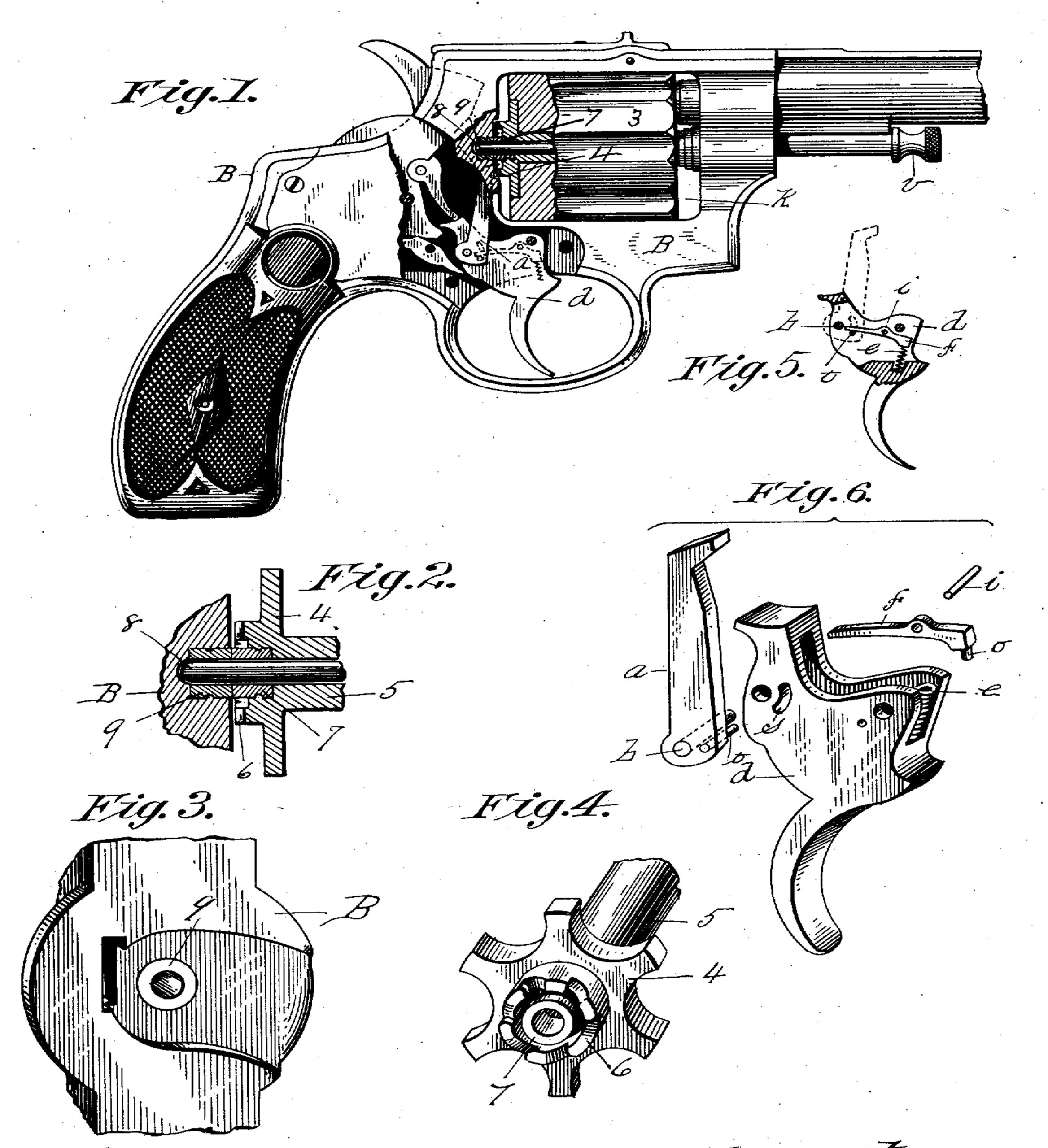
In the drawings forming part of this specification, Figure 1 is a side elevation of a revolver, partly in section, having our improvements applied thereto, a portion of the barrel being shown broken off. Fig. 2 is a sectional view of a portion of the frame and the shell-extracting spider. Fig. 3 is a perspective view of that part of the arm on which is the recoil-shield. Fig. 4 is a perspective view of the extractor-spider, the ratchet thereon, and of a portion of the stem thereof. Fig. 5 is a sectional view of the trigger and parts connected therewith. Fig. 6 illustrates in perspective the trigger and parts operating therewith much enlarged.
In the drawings, B is the frame of the arm, having an opening K of rectangular form therethrough, in which the cylinder 3 is held to be rotated, supported on a yoke swinging on the lower part of frame B laterally out of and into said opening, in the manner and for the purpose described in the patent to Daniel B. Wesson, No. 517,152, dated March 27, 1894. In said patented construction a central cylinder-holding pin 8 (herein illustrated in Figs. 1 and 2) has a sliding motion in the stem 5 of the spider 4, which stem occupies a position in the cylinder 3. The said sliding motion of said pin is into and out of a socket in the recoil-plate part of frame B, directly behind said cylinder in the position shown in Fig. 3, taken in connection with said Figs. l and 2. When said cylinder is in firing position in the arm, as in Fig. 1, said pin 8 occupies the position shown in said last-named figure. When it becomes necessary to swing said cylinder laterally to one side of the frame B, for extracting shells therefrom and for reloading it, the head v of said pin (shown under the barrel in Fig. 1) is grasped and the pin is drawn forwardly, thereby drawing its rear end out of engagement with said socket in the recoil-plate part of the frame. The parts of the arm directly adjacent to or in front of the central part of said recoil-plate are the ratchet 6 and the said spider 4. These last-named two parts are ordinarily of integral construction. As heretofore practiced, the portions of said spider and ratchet and the said recoil-plate against and in which said pin 8 moves, as described, have been substantially of the quality of ordinary forgings, and, consequently, not hard enough to resist the combined effects of abrasion and the shock produced by suddenly throwing the cylinder from an outward position into the frame and stopping the same by the quick engagement of the end of pin 8 in said recoil-plate. During said movement of the cylinder the extremity of said pin 8 is quickly moved inwardly and outwardly to the rear end of the cylinder. The effect of the last-described action often repeated upon said socket, when made directly in the recoil-plate, has been to more or less enlarge said socket, and also to result in a similar enlargement of the pin-perforation centrally through the said ratchet and spider. The consequence of said enlargement is sooner or later to disturb the requisite perfect alinement of the barrel and cylinder in the several firing positions to which the latter is brought, thereby producing inaccurate firing. To obviate the said inconvenience resulting from the wear or enlargement of said parts in which said pin 8 has its movement, a hardened metal bushing 9 is fixed in any well-known suitable manner in the position shown in said recoil-plate B to receive the rear extremity of said pin 8, and a like bushing 7 is fixed in said ratchet and spider part centrally within said ratchet, as clearly shown in Figs. 1 to 4, inclusive. The outer extremities of said bushings 9 and 7 extend, respectively, slightly beyond the plane of the face of said recoil-plate and of the teeth of said ratchet. Said bushings 7 and 9 are in practice preferably fixed in the relative positions illustrated in Fig. 2, that is to say, the outer adjacent ends of said bushings occupy mutually-abutting positions and constitute hardened rear-end bearings for the cylinder 3, and they thus serve to so hold the cylinder that the face of the ratchet 6 is maintained, unchangeably, in a position free from contact with the adjoining face of the said recoil-plate.
A further improvement in revolver construction herein shown consists in providing improved spring actuating devices for the pawl or hand a, which is hung on the trigger d and engages with the said cylinder-ratchet 6 to cause the cylinder to rotate coincidently with the pulling of the trigger. Said last-named improvements provide for a livelier and more reliable spring movement of said pawl than has heretofore been had, and the devices employed therefor are constructed and arranged as follows: The trigger d has a chamber formed between its sides, as shown in Fig. 6, and a spring e at one end of said chamber. A stiff lever f, having a stud o on one end entering and engaging with said spring, is pivoted within the said chamber on a pin i, (see Figs. 5 and 6,) and its free end engages the upper side of a bar t, projecting from said pawl through a curved slot s in the side of the trigger part way across said trigger-chamber.
Fig. 5 illustrates the above-referred-to trigger-containing parts in operative positions, the pawl being there indicated in dotted lines in the position which it and said spring and lever occupy when the pawl is engaged with said cylinder-ratchet. The pivot b of the pawl passes through the pivot-hole at the side of said curved slot s, and the said bar t, near said pivot, when said pawl has a swinging movement in passing over the ratchet-teeth, has a movement between the extremities of said slot, and said lever f has a corresponding vibratory movement, actuated in one direction by said pawl movement and in the opposite direction by the spring e, this latter action being one which causes the pawl to move toward and to be spring-retained against said ratchet.
Having thus described our invention, what we claim, and desire to secure by Letters Patent, is—
1. In a revolver, the cylinder having a hardened cylindrical bushing partly within and partly projecting from a recess in the rear end of said cylinder, the recoil-plate with a hardened cylindrical bushing flush with its front end, and a movable pin in position to enter both bushings and thus retain the bushings in line and with their faces in contact, all combined substantially as described.
2. In a firearm, the trigger having a chamber between its sides, a stiff lever pivoted within said chamber, and a spring bearing against one end of said lever, the pawl pivoted to said trigger and having a pin projecting through an opening in the side wall of the chamber and resting on one arm of the above-mentioned lever, all combined substantially as described.
DANIEL B. WESSON,
JOSEPH H. WESSON.
Witnesses:
H. A. CHAPIN,
K. I. CLEMONS.