
US 542744
UNITED STATES PATENT OFFICE.
DANIEL B. WESSON, OF SPRINGFIELD, MASSACHUSETTS.
REBOUND AND LOCKING MECHANISM FOR REVOLVERS.
SPECIFICATION forming part of Letters Patent No. 542,744, dated July 16,1895.
Application filed January 14,1895. Serial No. 534,916. (No model.)
To all whom it may concern:
Be it known that I, DANIEL B. WESSON, a citizen of the United States of America, residing at Springfield, in the county of Hampden and State of Massachusetts, have invented new and useful Improvements in Revolving Firearms, of which the following is a specification.
This invention relates to firearms, and more particularly to revolvers, and the object of the invention is especially to improve the cylinder-rotating mechanism and the mechanism for rebounding the hammer.
The novel features of construction and combinations of elements constituting the improvement are set forth in the claims, the more important parts thereof being the improved pawl or hand for rotating the cylinder, and the improved combination of elements for effecting the rebound of the hammer.
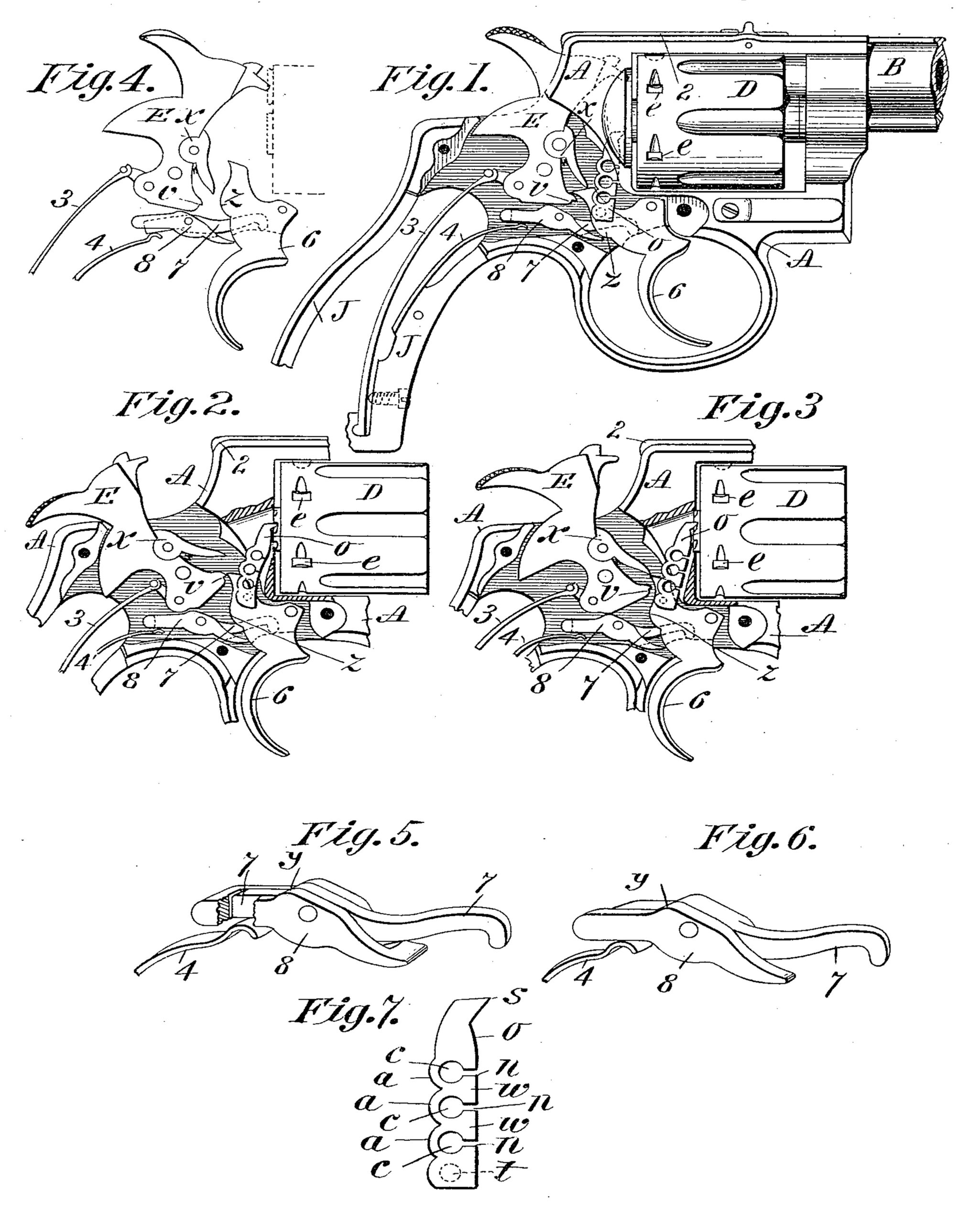
In the drawings forming part of this specification, Figure 1 is a side elevation, partly in section, of the central and a part of the handle portion of the frame of the cylinder and the lock embodying my improvements, this figure showing a short piece of the barrel of the arm. Figs. 2 and 3 are side elevations of central portions of the frame of the arm of the cylinder and of the lock parts of the arm. Fig. 4 is a side view of certain of the lock parts of the arm, showing parts of the main and trigger springs and indicating in dotted lines the relative position of the cylinder of the arm. Fig. 5 is an enlarged perspective view of detail parts of the lock mechanism hereinafter described. Fig. 6 is a perspective view illustrating a modified construction of the parts shown in Fig. 5. Fig. 7 is a side elevation of the pawl or hand connection with the lock parts of the arm and which engages with the cylinder thereof to rotate the same.
A is the frame of the arm, on which is the usual handle portion J. The hammer H, the trigger 6, and the mainspring 3 are of substantially the usual construction and arrangement in the class of revolvers known as “self-cocking” ones—that is to say, those which may be cocked and fired by pulling the trigger, but are ordinarily adapted, as is the arm herein described and shown, to be nearly full-cocked by pulling back the hammer by hand, and when so cocked the trigger engages the notch v of the hammer.
In cocking by pulling the trigger the extremity of the latter engages under the latch x on the hammer in the usual manner.
Fig. 2 illustrates the position of the hammer E when in full-cocked position, the trigger being there shown just ready to drop into said notch v.
The trigger-spring acts indirectly upon the trigger—that is to say, through the trigger-lever 7. Said lever 7 is pivotally hung on the frame A, one end thereof entering a recess between the sides of the trigger, as indicated in dotted lines in the drawings, and its rear end extends over the free end of the trigger spring 4, as clearly shown in the detail view, Fig. 5.
The rear edge of the trigger 6 has a projection z of curved form thereon, for a purpose hereinafter described.
The cylinder-moving pawl or hand o of the arm is pivotally attached to the trigger and has its upper extremity engaging with the usual ratchet-teeth on the rear end of the cylinder D, whereby the latter is rotated upon pulling the trigger.
The part which rotates the cylinder is known in the art both as a “pawl” and as a “hand.” I consider the term “hand” more appropriate in this instance, as the part has functions not usual with the pawl commonly employed and differing, also, from the “spring- pawl” or “yielding pawl” well known in mechanics. The hand o herein described yields to certain limit, when it becomes unyielding.
It is a well-known fact that the extent of the swinging action of the hammer of a revolver when cocked by hand and when cocked by pulling the trigger varies—that is to say, when the hammer is lifted by the engagement of the upper extremity of the trigger under the lower end of latch x the said trigger extremity swings, practically, to the position illustrated in Fig. 3, and the hand o, pivoted to the trigger, has a correspondingly-upward movement against the cylinder-ratchet to such an extent as to rotate the latter sufficiently to bring a loaded cartridge before the hammer, and when the cylinder reaches such position the usual cylinder-stop on the stop-lever 2 drops into one of the stop-notches e on the cylinder and rigidly holds the latter while the firing takes place. When, however, the hammer is cocked by hand, it requires a greater degree of back-swinging movement, so as to carry that portion of the hammer in which the notch v is located as high as the upper extremity of the trigger, (see Fig. 2,) so that the latter may engage in said notch. In imparting said additional rearward movement to the hammer, whereby it is brought to full-cock position, the part of the hammer on which the notch v is located is. moved from the position in which it is seen in Fig. 3 to that relative to the hammer-engaging point of the trigger, (shown in Fig. 2,) thus giving an additional endwise movement to the hand o. It will be noted that the said cylinder stop is engaged in one of the stop-notches e of the cylinder before the said additional rearward hammer-movement takes place. Therefore it follows, of necessity, that provision must be made whereby the engagement of the hand o with the cylinder-ratchet be not a rigid one. Otherwise the hammer could not be full-cocked by hand. The means heretofore resorted to for accomplishing the release of the hand from the cylinder-ratchet under said circumstances have consisted in a peculiar fit or adjustment of the hand and ratchet teeth, whereby the former may slip out of engagement with said teeth at the proper time and let the hammer have its full movement as aforesaid. Said peculiar fit or adjustment is liable to derangement from abrasion of parts, and is, owing to its nature, a comparatively-expensive construction.
In the firearm herein described and shown a hand o of novel construction is provided which overcomes all of the above-mentioned objections, and its construction and operation in the arm are as follows: Said hand, as shown, and particularly as illustrated in the enlarged side view in Fig. 7, is nearly of the usual outline form, and, as a result of its peculiar construction, it is made yielding or compressible, longitudinally, so that its point of engagement with the cylinder-ratchet is made invariably positive during the said additional rearward movement of the hammer. The preferable construction of said hand is that shown, but any other one may be adopted that will produce the same result without departing from the spirit of this invention relative to said hand. Said hand construction, as shown, consists of one or more partially-separated sections w, resulting from the transverse slots n in one edge of the hand, which communicate with the circular perforations c through the hand. The said sections w are united by the portions a of the rear border of the hand, which extend therebetween and which are formed in any suitable manner, whereby they are made sufficiently elastic to permit the point s of the hand, under suitable pressure thereupon, to be deflected toward its pivotpoint t. The action of said hand in operating the arm is as follows: The strength or capability of the elastic portions a of the hand is superior to the force required to turn the cartridge-cylinder when the latter is free to rotate, as it is when actuated in firing the arm by pulling the trigger; but when, as above set forth, the hand must yield or become shortened between its cylinder-engaging point s and its pivotal point t, the said elastic portions a yield, and, as the hammer reaches its extreme rearward or full-cock position, the deflection of said point s of the hand results in closing up the said slots in the edge of the hand, as shown in Fig. 2, and the hand then becomes longitudinally rigid, like one of ordinary construction. When the hammer falls and the trigger is released the hand resumes the position, as to said slots, shown in Figs. 1 and 3.
The rebounder-lever 8 is preferably hung on the trigger-lever pivot, as shown, and may be constructed of a flat-sided piece, as shown in Fig. 6, lying against the outer side of said trigger-lever, or of a piece longitudinally slotted, in which the last-named lever lies, as shown in Fig. 5. In either construction said two levers have independent action, as below described. The said rebounder-lever 8 has two arms, as shown, and has a free vibratory movement on its pivot, both when the hammer is at full-cock, as shown in Fig. 2, and when it is at its most forward position immediately after striking a cartridge, as shown in Fig. 1. The rear arm of said lever 8 is free to rest on the free end of the trigger spring, as shown, which spring thus becomes for the time being the rebounder-spring, and the extremity of its forward arm is free for contact with the projection z on the rear edge of the trigger when the nose of the hammer has retreated after firing. A projection or part y on the upper edge of the rebounder-lever is in position to engage the lower end of the hammer when the nose of the latter is to be retired from the primer of an exploded cartridge or “rebounded.” The swing of the trigger, then, forward to its normal position, whereby its upper extremity passes under the cocking-latch x on the hammer, brings the projection z on the rear edge of the trigger against the extremity of the forward arm of the lever 8, causing the last-named lever to swing on its pivot, and the part y on the upper edge thereof to be moved against the lower end of the hammer (see Fig. 1) thereby causing the hammer to swing slightly, and its nose to be retired rearwardly out of the plane of movement of the heads of the cartridges in the cylinder. With the lever 8 in the last-described position the hammer cannot be inadvertently forced forward against a cartridge. When the hammer is in the last-named position the two arms of the rebounder-lever 8 bear with nearly equal force against the trigger projection z and the free end of the trigger-spring, but with slightly more force against the end of said spring, whereby the pressure of the forward end of lever on the trigger is reduced, so that the pull of the latter in firing is made lighter or more sensitive.
Having thus described my invention, what I claim, and desire to secure by Letters Patent, is—
1. In a revolving fire-arm, a longitudinally yielding hand engaging with the cartridge cylinder for rotating the same, substantially as set forth.
2. The combination with the lock-mechanism and cylinder of a revolving fire-arm of a longitudinally yielding hand pivotally attached to the trigger and having its free end engaging said cylinder, whereby the latter is rotated, substantially as set forth.
3. In a revolving firearm, the cylinder having a ratchet connected thereto, and a hand 20 39 engaging said ratchet and operatively connected to the lock mechanism, said hand being a metal piece having one side continuous from end to end, the other side having surfaces separated by openings, whereby the piece becomes rigid when said openings are closed, all combined substantially as described.
4. In a gun lock, the pivoted hammer, the pivoted trigger having a cam or eccentric surface thereon, the rebounder spring, and the rebounder lever pivotally supported from the frame and between the rebounder spring and trigger,and having a cam surface engaging and rebounding the hammer from its extreme forward position when said lever is engaged by the cam on the trigger at about the extreme forward position of the trigger, all combined substantially as described.
5. In a gun lock, the pivoted hammer, the pivoted trigger, having a cam surface there- on, the rebounder spring, the rebounder lever supported on a pivot between said spring and the trigger, and having a cam surface in position for engagement with the hammer to rebound the same as described, the cam on the trigger engaging said lever, at about the extreme forward position of the trigger, and the cocking latch carried by the hammer and projected by a spring over the trigger when the hammer is in rebounded position.
6. The trigger having a projection on its rear edge, for engagement with one arm of a rebounding lever, a trigger-spring, a pivoted trigger-lever having one arm engaging with the trigger, and its opposite arm engaging said trigger-spring whereby the trigger is held normally in a forwardly swung position, combined with a rebounder lever whose upper edge at intervals has bearing contact with the lower end of the hammer, whose forward arm is alternately engaged with, and is free of, said trigger projection, and whose second arm is swung against said spring simultaneously with the said engagement of said forward arm with said projection.
DANIEL B. WESSON.
Witnesses:
H. A. CHAPIN,
Wm. S. BELLOWS.