
US 539497
UNITED STATES PATENT OFFICE.
DANIEL B. WESSON AND JOSEPH H. WESSON, OF SPRINGFIELD, MASSACHUSETTS.
REVOLVER.
SPECIFICATION forming part of Letters Patent No. 539,497, dated May 21,1895.
Application filed February 9, 1895. Serial No, 537,750. (No model.)
To all whom it may concern:
Be it known that we, DANIEL B. WESSON and JOSEPH H. WESSON, citizens of the United States of America, residing at Springfield, in the county of Hampden and State of Massachusetts, have invented new and useful Improvements in Revolving Firearms, of which the following is a specification.
This invention relates to revolving fire-arms having a cylinder which is adapted to be swung outwardly more or less to one side of the frame of the arm for the purpose of ejecting cartridge shells therefrom, and to provide for reloading the same; and is in the nature of an improvement upon Patent No. 517,152, dated March 27, 1894, to which reference may be had: the object being to provide improved mechanisms in an arm of this class for detaching these devices which retain the cylinder in firing position, and for restraining the cylinder more or less from being moved inadvertently, either outwardly or inwardly, and the invention consists in the peculiar construction and arrangement of said mechanisms, all as hereinafter fully described, and more particularly referred to in the claims.
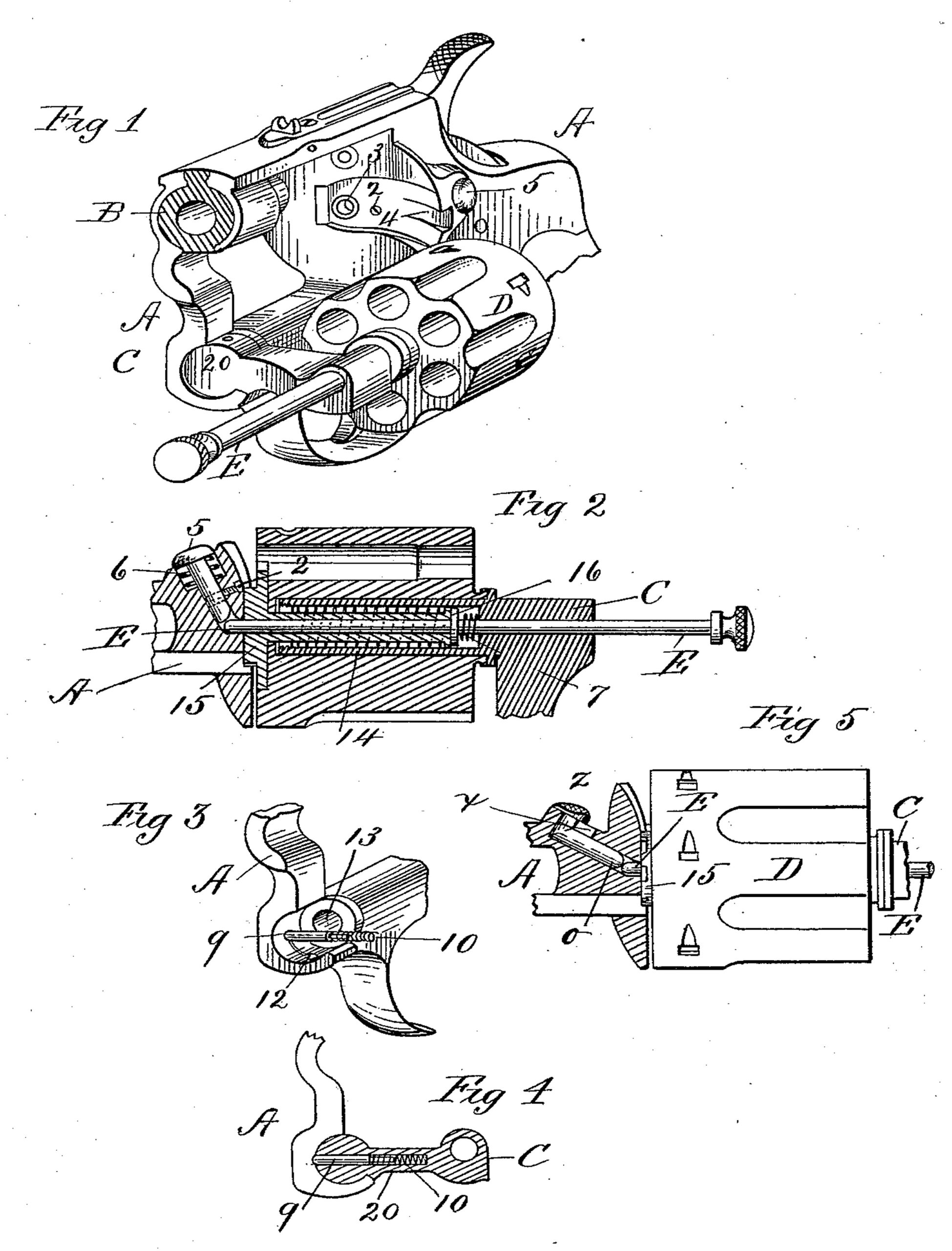
In the drawings, forming part of this specification, Figure 1 is a perspective view of that
part of the frame of a revolver in which the cylinder is located, together with the cylinder, which is shown in an outwardly swung position, all embodying our improvements. Fig. 2 is a longitudinal sectional view of the cylinder and a part of the frame, showing the cylinder and cartridge-supporting and cartridge-ejecting devices and illustrating certain features of our improvements. Fig. 3 is a perspective view of a portion of the frame of the arm, the operative position of a certain feature of our improvements which is hereinafter fully described. Fig. 4 illustrates parts of the frame and cylinder-yoke of the arm, showing the feature of said improvements which is illustrated in Fig. 3 applied in operative position in a part of the arm, all as hereinafter described. Fig. 5 is a side elevation of the cylinder, a portion of the ejector devices, and a section of a part of the frame, illustrating a modified construction of one of the parts shown in Figs. 1 and 2, all as hereinafter described.
In the drawings, A indicates a portion of the frame of the arm.
B indicates the breech-section of the barrel in the frame.
C indicates the yoke-frame on which the cylinder, D, is hung, said yoke-frame having a hollow arm, 14, (ordinarily termed a “ basepin”) on which the cylinder rotates, the operative relation of said hollow arm to the cylinder being clearly shown in Fig. 2. A second arm on said yoke-frame, C, enters a longitudinal chamber, 13, Fig. 3, in that part of the frame of the arm under the cylinder, and the yoke-frame, cylinder, and ejector devices, are all supported by said last named arm; and swing thereon when the cylinder is moved outwardly or inwardly. The usual cartridge shell ejecting spider, 15, is moved rearwardly from the cylinder by pushing on the cylinder-locking pin, E, after the cylinder has been swung out from the frame, as in Fig. 1, said pin, E, having a shoulder, 16, thereon which engages the end of the hollow-shank of said spider. A spring, 7, is interposed between said shoulder, 16, and the base of the chamber in the arm, 14, which throws said pin, E, toward the recoil-plate of the arm, and causes its rearward extremity to enter the socket, 3, therein (see Fig. 1) thereby serving to retain the cylinder, D, in firing position in the frame A. The cylinder is automatically locked by said pin, E, when swung into the frame for its extremity follows the inclined base of the groove, 4, in said recoil-plate and is thus caused, first, to recede toward the end of the cylinder, and then to enter said socket, forced by the spring, 7, as aforesaid. The construction as shown in said patent makes it necessary that while the arm is held in one hand the other must be used to draw the pin, E, forward and free its rear extremity from said socket in the recoil plate, in order to free the cylinder, D, so that it may be swung to one side of the frame as in Fig. 1. Said mode of operating said cylinder-locking pin is at times inconvenient, and finding it desirable to so improve the arm that the cylinder may be disengaged and swung outwardly while held in the firing hand and without using the other, we have provided the below described means for disengaging said locking-pin, E.
A suitable boss or thickness of frame is provided back of the recoil-plate, which is perforated to receive a headed bolt, 5, (Figs. 1 and 2,) having an inner extremity suitably tapered for such engagement with the extremity of the locking-pin, E, that when said bolt is pressed inwardly, said pin is moved out of engagement with the recoil plate; and while said bolt is so held by the thumb of the hand in which the pistol is carried, a sudden turn of the hand in the direction of the out-throw of the cylinder, and back again, leaves the latter in the position shown in Fig.1. By then pushing the outer end of the pin, E, against any suitable object, the shells may be ejected from the cylinder, and the latter be then again reloaded. Said bolt, 5, has a slot through it into which a screw, 2, enters, whereby it is secured in the arm and prevented from turning in its socket. A spring, 6, is placed under the head of said bolt whereby it is held in the position shown, ready to be driven against said locking-pin. A modification of the construction of said bolt, 5, is illustrated in Fig. 5, wherein the said spring, 6, is dispensed with, said modification being as follows: A similar perforation is made in the frame-part, A, of Fig. 5, to that made in the like part of Fig. 2, communicating with the base of the socket in the recoil-plate, which receives the rear end of said locking-pin, E. The opening from the main part of said perforation outwardly through said frame part is in the form of a slot, x. The shank of said bolt, z, lies in said perforation with its inner end normally against the rear end of the pin, E. The neck of the head of said bolt, suitably attached to said shank, extends through said slot, and the head proper lies in convenient position to be pressed upon with the thumb (as is said bolt, 5), to drive it against pin, E, for the purpose aforesaid. That part of the bolt which carries the head may screw into the side of the body of the bolt, as is common in door bolts. The said movement rearwardly, of the pin, E, actuated by said spring, 7, serves to bring the ends of said pin and bolt to the relative positions shown in Fig. 5, with no other spring than that which actuates the said pin.
It is found desirable in this class of revolvers to provide some means for preventing a too free escape of the cylinder from the frame after the locking-pin, E, has been withdrawn; and a too free commencement of the movement of the cylinder from its most outward position toward its firing position after loading the same, the object of said prevention being to guard against any possible inadvertent movement of the cylinder in the directions stated, and to provide for such retention of the cylinder in its out-swung position as shall guard against any accidental in-swinging movement before it shall have received its full number of charges. To this end there is placed in a perforation in the forward arm, 20, of the yoke, C, a sliding-pin, 9, having an outer end for temporary engagement in sockets, 12, 12, in the inner wall of that part of frame, A, in which one end of said arm, 20, has an oscillating movement when the cylinder swings as aforesaid. Said sockets are so located as to receive the end of said pin,—one, when the cylinder is in the frame, and one when it is swung outwardly. Said pin, 9, has an inner end of reduced diameter, thereby forming an annular shoulder thereon, and it is of less length than the depth of the perforation in which it is. A spring, 10, moves the pin outwardly, and its outer end slides over the surface of the part in which said perforations are, and in and out of said perforations when the cylinder yoke, C, is given said oscillating movements, but its outer extremity has sufficient engagement with each of said perforations to effect the above-described object.
Having thus described our invention, what we claim, and desire to secure by Letters Patent, is—
1. In a revolver, the main frame and a yoke-frame hinged therein, the cylinder carried by the yoke frame, a centrally located cylinder locking pin having a rearward movement into a recess in the recoil plate to lock the cylinder and yoke in the frame, and a push pin in the rear frame in position to engage said locking pin to detach the same, all combined substantially as described.
2. In a revolver, the main frame and the side swinging yoke frame hinged thereto, the cylinder carried by said yoke frame and the spring pressed center pin extending through said cylinder and entering the recess in the recoil plate to lock the cylinder and yoke in place as described, and the spring push pin extending obliquely through the recoil shield in position to engage said center pin to unlock the same, all combined substantially as described.
3. The combination with the cylinder of a revolving fire-arm, the yoke-frame thereof on which it swings laterally, and the frame of the arm, of a spring-actuated, movement-restraining pin carried in said yoke-frame and having contact by one end with the frame of the arm, substantially as set forth.
4. The combination with the cylinder of a revolving fire-arm, the yoke-frame thereof on which it swings laterally, and the frame of the arm having one or more pin-sockets therein, of a spring-actuated, movement-restraining pin carried in said yoke-frame which is alternately engaged with and disengaged from said sockets, substantially as set forth.
DANIEL B. WESSON.
JOSEPH H. WESSON.
Witnesses:
H. A. CHAPIN,
WM. S. BELLOWS.