
British 2050
LETTERS PATENT to William Castle Dodge, of Washington City, District of Columbia, United States of America, for the Invention of “ Improvements in Fire-asms.”
Sealed the 2nd February 1866, and dated the 7th August 1865.
PROVISIONAL SPECIFICATION left by the said William Castle Dodge at the Office of the Commissioners of Patents, with his Petition, on the 7th August 1865.
I, William Castle Dodge, of Washington City, District of Columbia* United States of America, do hereby declare the nature of the said Invention for “ Improvements in Fire-arms,” to be as follows :—
My Invention relates to that class of fire-arms denominated many-chanlbered, and in which metallic cartridges are generally used ; it consists primarily in the simultaneous and rapid removal of the cartridge cases or shells from the arm, and in certain devices adapted to produce that result
The principal device used in my Invention is the retractor, which removes the cartridge cases. This consists of a metallic plate of any suitable form to adapt it to the arm to which it is to be applied, and is so constructed as to fit snugly against or within the end of the barrels or cylinder from which the cases are to be removed ; it has portions so. cut away as to form openings or recesses corresponding with the chambers, as shown in Figures 7, 9, 10, 11, 12, 13, and 16. This plate a is provided with a stem b9 or its equivalent, by which it is held, guided, and operated. On this stem is placed a spiral spring c, secured by a nut d. By these means the plate a is brought close up against the end of the cylinder or barrels, so that when the cartridges are inserted their flanges or rims will rest in whole or in part against the outer face of a. As already stated, this retractor plate a may be of any suitable form ; it may be a perforated disk, as shown in Figure 13, in which case it will lie flat against the end of the cylinder or barrels, or it may be in the form of a smaller disk, with sections cut away, as shown in Figures 7, 9, and 10, or what is technically known as a “ spideror it may be a perforated disk, with portions cut away as indicated in red lines in Figure 13. When either of the latter forms of a is used, the end of the cylinder or barrel should be so recessed as to cause the outer surface of a to come flush therewith. To permit the use of this retractor the cylinder (in revolving arms) must be so attached to the frame that the end which receives the cartridges can be swung or moved clear of any obstruction, such as recoil plate E or other portions of the frame. This I accomplish by so pivoting the frame to which the barrel is attached as to permit it being moved in a vertical plane, as shown in Figure 1, or in a horizontal plane, as shewn in Figure 9, in which latter case the face of the recoil plate E will necessarily be made concave, as shown in Figure 15, in order to permit the cylinder to swing clear, and yet be brought in close contact therewith when in position for firing. In those arms whose barrels do not revolve the object is accomplished by so hinging them that the end may be elevated, as shown in Figure 6, or in other suitable manner. In order to permit the passage of the stem b through the cylinder, and at the same give the latter a suitable bearing, I attach the cylinder to the frame by means of the tubular bolt or stud g, which is secured to the frame at one end only, and upon which the cylinder is secured by a proper head or nut, as shown in Figure 2, where the parts are shown in section; or it may be attached by means of the neck or journal h> as shown in Figures 11 and 12. By this last method I am enabled to use a retractor stem as large as bolt g without enlarging the cylinder; or by making the stem slightly less in diameter, the spring c may be seated within the cylinder, the central bore being properly chambered for that purpose, as clearly shown in Figures 11 and 12, by which means room for the operation of the spring c is obtained without having the stem b protruding so far as it necessarily would when the spring is applied entirely outside of the cylinder, as in Figure 2, and thus the danger of bending or otherwise injuring the stem 6 is greatly decreased.
In applying my Invention to those revolving arms whose cylinders are charged at the front instead of the rear, it will be necessary to attach the cylinder to the recoil plate E or rear portion of the frame, as shown in Figure 1, in which case the use of the tubular bolt or stud would be preferable. In such cases the barrel must be pivoted as to move in a vertical plane, in order that it may be removed from the front of the cylinder for the purpose of permitting the proper use of the retractor for the ejection of the cartridge cases. For the purpose of rendering the cylinder more secure in its position, and ensuring the coincidence of its chambers with the bore of the barrel, I provide it with a moveable bearing or sapport at the end opposite that which is attached to the frame. Tnis I do by causing the stem b of the retractor a to pass through and project outside of plate a, as shown at i, Figures 1, 9, 11, 12, and 13. This projection i enters a corresponding groove j in plate E or other portion of the frame, which groove is clearly shown in Figures 11,14, and 15. By thus giving to the rear of b a firm support, I am enabled to dispense with the bolt g and journal A, and suspend the cylinder B entirely upon the retractor stem 6, the latter of course passing through a proper hole in the post e of frame C. In order to operate the retractor in such case the cylinder B must be held close up to plate E, and not allowed to move back with the retractor when the latter is shoved out to eject the cartridge cases after being swung outward from E for that purpose; this may be accomplished by a slight projection from the under side of bridge piece p passing down over the edge of the end of the cylinder, but not so far as to interfere with the operation of the retractor; or said projection may engage in a circumferential groove on the periphery of the cylinder; or it may be accomplished by any suitable means. This method of hanging the cylinder I do not consider as good as the others, and it will only be desirable where the object is to make a very small revolver. For the purpose of locking the cylinder securely in its place in position for firing, a latch k is pivoted in a proper recess in the face: of plate E, the upper edge of the said latch coinciding with the upper edge of groove j in its rear. Near its centre longitudinally, and at the centre of E,. where it is desired that i shall rest, this latch k is provided with a notch or semicircular recess in its upper edge, which recess engages with and holds i firmly in place after it has been forced to its seat in groove j, the latch k being held up by a spring that yields to the pressure of i upon the inclined end of k, thereby permitting j to pass into its seat. Within a vertical hole bored in plate E near its right side or edge is placed a catch bolt Z, which has its upper end bevilled, as shown in Figure 14, and which bolt is pivoted to latch k by means of pin m, which passes through both, working in a vertical slot in E, and is provided with a suitable head or thumb-piece, as shown at m, Figures 9,11, and, 1,5. Bolt l and latch k are both forced upward by spring o, as shown in Figure 11. The rear portion of bridge-piece p is provided with a statable groovy which engages with a corresponding projection on the top of E, by which the swinging and stationary portions of the frame are secnnely united when brought into position, and when thus united the parts are locked together by the catch bolt l engaging in a suitable recess in the under side of py as shown in dotted lines in Figure 11. If desired, the latch bolt b may be located in bridge-piece jp, and provided with a suitable head q, as shown in Figure 2. If desired, the lock joint of the frame C may be located at any intermediate point on bridge-piece p, as shown at v, Figure 4; or the frame may be pivoted at the front of p, as shown in Figure 3.
In order to render the arm more strong and durable I construct the pivot joint as shown in Figures 2 and 11, in which t and u are journals working within a sleeve, whereby a very strong joint having a long bearing is secured. In order to render the arm still more perfect and secure it against accidental discharges I provide it with a hammer of novel construction. To provide for using the simplest form of lock the lower end of the hammer D is located centrally within the stock F, by which means the hammer and tumbler con be formed of one piece. The body of the hammer as it rises above the stock is then curved to one side, as shown in Figure 5, for the purpose of affording more room for the thumb to operate the thumb-piece ro, and thereby the bolt l and latch k for unlocking the parts. By thus curving the hammer its point u) is brought into such a position that it strikes the rim of the cartridge which contains the fulminate along one side of its face, as shown in Figure 14, where the position of the cartridge is indicated in red. By this means the face of the hammer is made to cover a much larger portion of the fulminate than where it strikes radially across the rim in the usual manner. I then so construct and locate the hammer that no portion of it projects above the bridge piece p, by which means I prevent the accidental discharges so often caused by the projecting hook or thumb-piece on the top of the hammer, as usually constructed, catching in the holster case or pocket when the pistol is inserted therein* Instead of having the hook project upwards in the usual manner, I curve it backward, as shown at x, Figure 2, and unite its rear end with the body of the hammer at or near the curve therein, by which it is prevented from catching in the holster case or pocket when the pistol is withdrawn therefrom. Any object coming in contact with x will be thereby so deflected as to pass above and clear of bridge-piece p.
The application of my Invention to arms whose chambers or barrels do not revolve is clearly shown in Figures 6, 7, and 8. In such cases the retractor stem 6, instead of projecting at the end of the cylinder or barrel, is simply seated within a suitable bole centrally between the barrels. Before it is thus inserted a* collar y, having a hole through its centre and a screw thread cut on its periphery, is slipped on the stem b, after which the spring c is placed thereon and secured by nut d on the end of the stem, as shown in Figure 8. The collar y is then screwed into its seat at the mouth of the central hole, in which the stem and spring are inserted. The nut d corresponding in size With the central hole, and the stem b fitting accurately in the collar y, through which it passes, it follows that the stem b and retractor plate a will be so guided as to cause them to move in a straight line parallel with the bore of the barrels. The plate a is provided on its two opposing edges with a roughened projection, as shewn at z, z, Figure 7, by which it is readily grasped between the thumb and finger and drawn outward from the end of the barrels* thereby removing at once all the cartridge cases, whatever their number. When released the retractor a is instantaneously and automatically returned to its original position, thereby rendering the arm ready for being reloaded. If desired, the same arrangement of the retractor may be adopted with revolving cylinders, the stem b in such case being made shorter, and thus prevented from projecting beyond the end of the cylinder or the face of the frame C. In such cases it is obvious that the retractor must be operated by drawing it outward, as in Figure 8, instead of pushing it by pressing on the end of b, as in Figures 2, 9, 11, and 12. In such case the edge of plate a, Figure 13, may be milled or otherwise roughened to secure a firm hold, or proper recesses may be made in the sides of the cylinder B at that end where -the plate a is applied. If desired, the stem b, in Figures 11, 12, and 8, may be provided with a feather having a corresponding seat in the journal h or collar y, by which its movement will be so guided as to canse the plate a to return to its seat in such a position that its perforations or recesses shall exactly coincide with the chambers of the arm; or the same result may be produced in these cases, and also when the tubular bolt g is used, by attaching to the inner face of a one or more pins or stems working in corresponding holes or recesses in the cylinder or barrels. In practice, however, these arrangements are not found necessary, as the plate a is easily shoved into its proper position by the point of the bullet when the latter is inserted in re-, loading the arm. In the case of stationary chambers, as shown in Figure 0, the retractor may be operated by the lock bolt a\ which is provided with a head at b1 for operating it. In such case it is only necessary to connect the bolt a1 to plate a or stem b in any suitable manner, the simplest form of which in indicated by Figure 6, where the red lines represent an arm projecting from a1 in such a position as to engage with and operate the retractor a when-a1 is shoved backward. The form or method before described and shown in Figures 6 and 7 is, however, considered preferable, as it is simple, compact, and not liable to be easily broken or disarranged by ordinary use. This method of applying my Invention is peculiarly applicable to the arms known as Elliotts repeater and Sharpes repeating pistol, and to all arms similarly constructed. It is obvious that the methods here shown of applying my Invention may be so modified as to eject a portion only of the cartridge cases” at once, but that would be a mere modification, and one that I do not deem desirable.
SPECIFICATION in pursuance of the conditions of the Letters Patent, filed by the said William Castle Dodge in the Great Seal Patent Office on the 2nd February 1866.
TO ALL TO WHOM THESE PRESENTS SHALL COME, I, William Castle Dodge, of Washington City, District of Columbia, United States of America, send greeting.
WHEREAS Her most Excellent Majesty Queen Victoria, by Her Letters Patent, bearing date the Seventh day of August, in the year of our Lord One thousand eight hundred and sixty-five, in #the twenty-ninth year of Her reign, did, for Herself, Her heirs and successors, give and grant unto me, the said William Castle Dodge, Her special licence that I, the said William Castle Dodge, my executors, administrators, and assigns, or such others as I, the said William Castle Dodge, my executors, administrators, and assigns, should at any time agree with, and no others, from time to time and at all times thereafter during the term therein expressed, should and lawfully might make, use, exercise, and vend, within the United Kingdom of Great Britain and Ireland, the Channel Islands, and Isle of Man, an Invention for “ Improvements in Fire-arms,” upon the condition (amongst others) that I, the said William Castle Dodge, my executors or administrators, by an instrument in writing under my, or their, or one of their hands and seals, should particularly describe and ascertain the nature of the said Invention, and in what manner the same was to be performed, and cause the same to be filed in the Great Seal Patent Office within six calendar months next and immediately after the date of the said Letters Patent.
NOW KNOW YE, that I, the said William Castle Dodge, do hereby declare the nature of the said Invention, and in what manner the same is to be performed, to be particularly described and ascertained in and by the following statement thereof, that is to say :—
My Invention relates to that class of fire-arms in which the charge is used enclosed in a metallic ease or tube, or one composed partially of metal and partially of other material, the prime object of my Invention being the speedy removal of the cartridge cases or tubes from the chambers of a many-chambered fire-arm.
My Invention consists, first, in constructing and applying to the arm a mechanical device for withdrawing or ejecting the shells, which I denominate a retractor; it further consists in novel methods of constructing the arm to permit the retractor to be applied and used, and various devices for operating the parts.
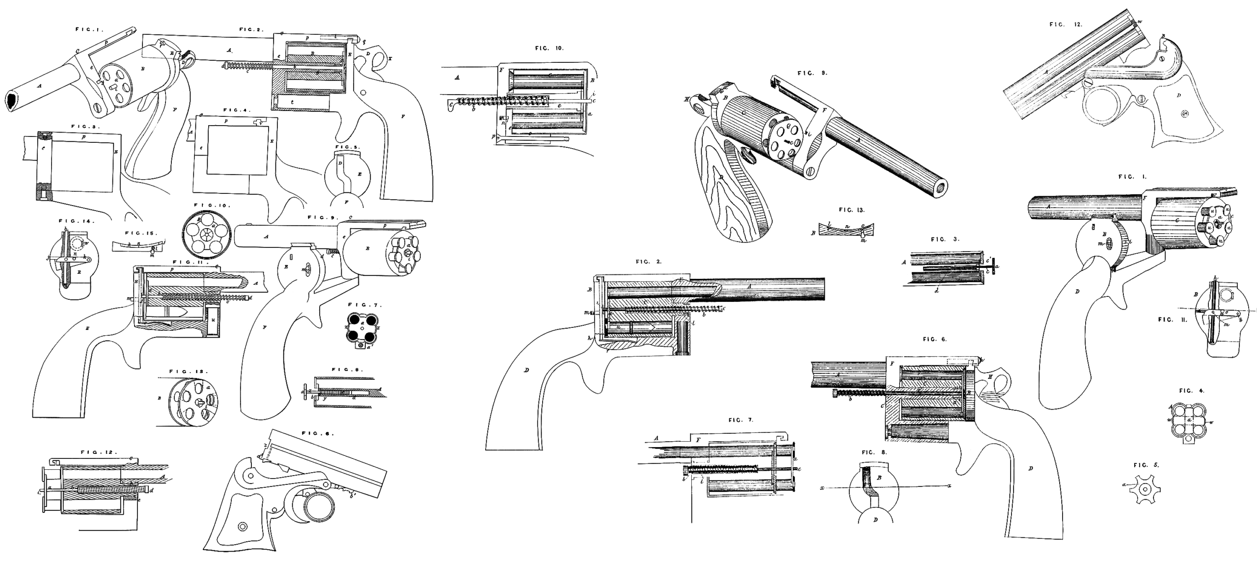
In the accompanying Drawings, which form a part of this Specification, Figures 1, 2, 5, 6, 7, 8, 9, 10, 11, & 13 represent various parts and styles of revolving arms with my improvements applied.
In the various Figures, wherever they occur, the letters A indicate the barrel; C, the cylinder; B, the breech or recoil block; F, the frame to which the barrel is secured; and D, the stock or handle. The cylinder C in all cases, except as shown in Fig. 9, has its chambers bored entirely through it longitudinally, so that the cartridges u can be inserted at the rear end of said cylinder, as shown in Figs. 1 & 2, the cartridges being provided at their rear end with a radially projecting flange, which may or may not contain the fulminate as desired. The retractor consists of a metallic plate a fitted against the end of the cylinder, as in Fig. 9, and having holes in it to correspond with the chambers of the cylinder, so that when the cartridges u are inserted through said holes into the chambers of the cylinder, the flanges of the cartridges shall rest against the outer face of said retractor or plate a. When thus constructed, the plate a may consist of a section of the cylinder itself, cut transversely of any required thickness, though in practice I find it both easier and cheaper to form the retractor of a separate piece. I also construct the retractor for this class of arms as shown in Figs. 1 & 5, in which form it consists of a plate fitted to rest in a recess formed for it in the end of the cylinder. Semicircular notches are cut in its periphery, so as to correspond with the chambers in the cylinder, the extreme diameter of the plate a in these cases being such that when the cartridges are inserted the notches in the plate a will encircle one-half of the circumference of the cartridge, the flange of the latter resting half way around against the face of the plate a, as shown in Fig. 1. It is not, however, necessary that the plate a should thus encircle the cartridge, it being sufficient if a small point only of the plate engages underneath the flange of the cartridge. Hence it is obvious that the retractor plate a may be modified in form to a great extent, the only requisite being that it shall be provided with openings or notches to permit the insertion of the cartridges, and have some portion of it engage underneath or in front of the flange on the cartridges. If desired it may be constructed in the form of a core, fitting in a suitable hole in the center of the cylinder, its diameter being such that its periphery shall form a portion, more or less, of the walls of the chambers of the cylinder, said core extending wholly or partially through the cylinder longitudinally, as may be preferred. This form of retractor, however, is not so cheap to make, nor do I consider it so good as those previously described, for the reason that when thus constructed an opening will necessarily extend from one to another of the chambers in the cylinder, thereby rendering the arm unsafe to use. In order to operate the retractor a, I attach it to a stem* c, by which it can be shoved back, as shown in Fig. 7. In order to have this stem c occupy a central position longitudinally of the cylinder, I mount the cylinder on a tubular bolt e, as shown in Figs. 6 & 10, the stem c extending through said bolt e, and projecting at the front end, as shown in Figs. 2, 6, 7, & 10, so that by pressing back on the projecting end of the stem c the retractor a may be shoved back, and carry out the shells or cases with it from the chambers of the arm. In order to bring the retractor back to its position ready for re* loading the arm, a spring b is applied around the stem c, as shown in the Drawings. In Figs. 2 & 7 the tubular bolt e is dispensed with, the cylinder C in such cases being secured to the frame F by means of a tubular journal L In order to support the rear end of the cylinder in such cases, the end of stem c is made to protrude beyond the outer face of plate a, and enter a groove or recess i cut for it in the breech block B, as shown in Figs. 1, 2, 9, 8s 10, the groove i being shown more clearly in Fig. 11, which is a front view of the breech block, a portion being broken away to show the bolt h. In all cases it is necessary that the end of the cylinder from which the cartridge cases are to be ejected shall be exposed or moved away from in front of the breech B, so as to permit the retractor to be shoved back, and thus remove the shells. In Figs. 1 & 2 the frame F, with the barrel A and cylinder C attached thereto, is shown pivoted to that portion of the frame which is below the cylinder, so that the barrel and cylinder may be swung -around in a horizontal plane, by which means the rear end of the cylinder •can be exposed, as shown in Fig. 1, which represents the cylinder moved, and the retractor a with the shells u partly thrown back. Fig. 6 represents the frame pivoted so as to move in a vertical plane, the construction and operation otherwise being the same.
Fig. 9 represents a revolver in which the cartridges are inserted at the front end of the cylinder. In such cases the cylinder C is hung to the breech block B, the tubular bolt e or hollow journal t either being used, as may be preferred, and the frame F with the barrel A being pivoted to move in a vertical plane away from the front end of the cylinder, and thus permit the retractor a to shove the cartridges out. In this case the retractor stem c may be made to protrude through the breech B, the hammer H being secured to one side of the arm; or if located centrally of the stock, it may be curved to one side, as shown in Fig. 8, so as not to interfere with the protruding stem c; or the stem c may be so made as not to protrude, the retractor in such case being operated by taking hold of its edges and drawing it forward away from the end of the cylinder. In all cases where the frame is constructed in two parts, and pivoted as described, the rear upper portion of frame F has a groove cut in it, so as to lock with the top of breech B, and thus unite the parts firmly, as shown in Figs. 1, 2, 6, 7, & 9. In order to lock the parts together, a lock bolt h is located vertically in the breech B, as shown in Fig. 11, and operated by a spring r, as shown in Fig. 2, or in any other suitable way. The upper end of bolt h protrudes so as to engage in a recess provided for it in the under surface of the rear portion of the frame F, the end of said bolt being bevelled, so as to be shoved down when struck by the frame F as the latter is swung into place. This bolt is provided with a thumb-piece m (see Figs. 1 & 2), which protrudes from the rear face of B, it working in a slot cut therein, and extending through and being secured to bolt hy see Figs. 2 & 11, so that by pressing down on m the bolt h may be depressed, and the frame unlocked preparatory to exposing the end of the cylinder for throwing out the shells. Where the journal t is used instead of the bolt e> and it is desired to Jock the rear end of the cylinder more securely id place, I pivot a latch o, as shown in Fig. 11, at lt in a suitable recess in the face of B. This latch o has a notch n at. the center of the front face of B, to receive the projecting rear end of stem c when it enters groove i, the end of latch o being bevelled, as shown, so that it will be depressed when hit by stem c, and permit the point of c to. pass into the center, where it is locked by being engaged in the notch n of latch o, the Jatch being pivoted to the bolt h by having the end of m extend through both, as shown in Fig. 13, which is a transverse section of B, taken on the line ir, #, of Fig. 8, so that both may be depressed together by simply .pressing pn the thumb-piece one spring also serving to operate both. By these means both the frame and the cylinder are independently locked in position, both locking automatically as they are swung into position, and both being released by a single operation. It is obvious that this double locking arrangement may also be used in connection with a cylinder mounted on the bolt *, but it is not considered necessary in that case, as the cylinder is supported through its entire length by the bolt e being secured rigidly to the frame F, it being either formed solid with the frame, or having its front end screwed into the frame, as may be preferred. The only object of using the journal t instead of the bolt e in any case is where a very small cylinder is used, and there is not sufficient room to permit the use of the tubular bolt e and the stem c with the spring b therein. Where it is not desired to use the additional locking device 0, the bolt h may be located in the upper bar of frame F, and made to engage in notch or recess in the front face of the upper portion of B, the bolt h being shown thus arranged by the red dotted lines in Fig. 6, the notch in which it engages being shown at a1 of Fig. 9.
Fig. 10 represents my improvements applied to an arm having the frame F made solid instead of in two separate parts, as in those previously described, this style being more especially adapted to large arms, such as rifles and shot guns, whether intended for military or sporting purposes. In this style of arm the tubular bolt e is secured at its front end to an inner frame e\ the lower arm ol of which is bored longitudinally, and secured within the frame F by the bolt p, which thus forms a pivot, on which the frame el may be moved to one side, thus swinging the cylinder C out of the frame F, when the retractor can be operated as previously described. If the stem c be allowed to protrude, as shown in Fig. 10, the side of the vertical front bar of frame F will necessarily have a recess formed in it to receive the stem c. A spring catch n1 is located in the front bar of frame F, and arranged to hold the frame e\ and of course the cylinder C, securely in position, so as to ensure the chambers of the cylinder coinciding perfectly with the bore of the barrel. If desired the additional locking latch 0, or its equivalent, may also be used at the rear end of the cylinder. To use a cylinder loading at the front in this style df frame, it is only necessary to reverse the position of the inner frame e\ so as to have it support the cylinder at the rear instead of at the front. I construct the hammer H of the form shown in Fig. 6. When thus constructed and arranged it will be observed that the top of the hammer is lower than the top of the frame F, so that when the pistol is thrust into a holster or pocket there is no danger of an accidental discharge by having the top of the hammer catch and be raised, as. frequently happens with the: arm as usually constructed. Instead of the backward projecting hook usual on the top of the hammers, I curve it downward, and unite it to the body of the hammer, as shown, so that the danger of catching it in the pocket or holster when an attempt is made to withdraw the pistol is obviated. If the hammer be located on the side instead of centrally, the hook may be carried still further back at its lower portion, and joined to the body of the hammer still lower down. By curving the hammer as shewn in Fig. 8, it is made to strike the cartridge lower down than usual, as it hits the cartridge along one side of its face, as shown in dotted lines in Fig. 11, which enables me to lower the point of the hammer. By striking the cartridge thus, the point of the hammer is also made to cover a much larger portion of the flange containing the fulminate, and thereby render the ignition of the charge more certain.
In Figs. 3, 4, & 12 my retractor is shown applied to a many-chambered arm, having stationary in contradistinction to revolving cylinders. A represents the barrels, of which, in this case, there are four, but any number may be used. In Fig. 12 these barrels are shewn hinged to the stock D in such a manner that their rear end can be tipped up to remove them from in front of the breech B. It is, however, obvious that instead of tipping the barrels as there shown, they may be arranged to slide forward, or swing sidewise, and thus open their rear ends with similar results. To apply my improvement to these styles of arms, I simply bore a hole centrally between the barrels, and parallel therewith, into which I insert the stem c of the retractor a, first slipping on to the stem c a small collar c1, with or without a screw thread cut on its exterior ; then the spiral spring, which is secured by a nut d, the collar c1 serving to hold the parts securely in place, as shown in Fig. 3, which is a longitudinal section of the barrels with the retractor applied. It will be understood that the plate a will be made of any required form to adapt it to the form and number of barrels which the arm may have, and as the stem c is not intended to protrude from the front, as in the case of the revolvers, a projection w is made on two opposite edges of plate a, so that it may readily be grasped by the thumb and finger, and thus operated. Instead of making the plate as shown at Fig. 4, the retractor may consist simply of a flat bar fitted in a recess in the end of the barrel, and of sufficient width to slightly engage with the flanges of the cartridge shells. This bar may be arranged either horizontally, as indicated by the red lines in Fig. 4, or vertically. In all cases where the retractor is to be operated by drawing it by the thumb and finger, instead of by the protruding stem c, it may be secured to the barrels by means of one or more arms or rods working in
grooves in the sides of the cylinder or barrels, or in holes bored parallel with the chambers, instead of attaching it by the central stem c. Instead of making it in one piece, so as to throw out all the shells at once, it may be made in two or more parts, and each arranged to operate independently; but these plans are but mere modifications of my general plan, and are neither as simple nor as cheap. It will be necessary when the retractor is applied to the rear end of a revolving cylinder to place the ratchet by which the cylinder is rotated on the plate a instead of on the cylinder itself, as shown in Figs. 1 & 6. In all cases the retractor may be kept from turning if desired by means of a feather working in a groove; but in revolvers, as the chambers are of uniform diameter and equidistant, this is not necessary in practice.
Having thus fully described my Invention, what I claim and desire to secure by Letters Patent is,—
1st, the simultaneous ejection of the cartridge shells from a many-chambered fire-arm, whether loaded at the front or rear, and whether having revolving or stationary chambers, substantially as and by any of the means herein shown or described.
2nd, I claim mounting the cylinder of a revolving fire-arm on the tubular bolt e or hollow journal f, substantially as and for the purpose set forth.
3d, I claim supporting the rear end of the cylinder C by means of th& projecting end of the retractor stem c resting in the groove £, as described.
4th, I claim the pivoted frame F arranged to turn either in a vertical or horizontal plane, and provided with the locking devices, substantially as shown and described.
5th, I claim mounting the cylinder C in an independent frame arranged to swing in and out of the stationary frame F, substantially as shown in Fig. 10.
6th, I claim the retractor a arranged to operate in combination with a many-chambered fire-arm, either with or without the spring b9 for the purpose of removing the cartridge shells therefrom, substantially as herein described.
In witness whereof, I have hereunto set my hand and seal, this 12th January 1866.
WILLIAM CASTLE DODGE. (l.s.)