
British 2228
LETTERS PATENT to William Tranter, of Birmingham, in the County of Warwick, Gun Maker, for the Invention of “ Improvements nr Firearms.”
Sealed the 10th December 1868, and dated the 1st August 1867.
PROVISIONAL SPECIFICATION left by the said William Tranter at the Office of the Commissioners of Patents, with his Petition, on the 1st August 1867.
I, William Tranter, of Birmingham, in the County of Warwick, Gun Maker, do hereby declare the nature of the said Invention for “ Improvements nr Fire-arms,’’ to be as follows:—
My Invention relates to breech-loading fire-arms, and has reference to the Inventions described in the Specifications of two Patents granted to me, and bearing date respectively 20th July 1865, No. 1889, and 17th August 1866, No. 2113, and consists, in the first place, in elongating the screw for closing the r£ar end of the plunger by forming a tube with a hook at the front end thereof for the purpose of retaining the striking pin in order to prevent its falling accidentally and igniting the cartridge after it has been inserted in the barrel. By means of this arrangement the gun can be carried with safety when loaded, and when required to be fired it is only necessary to turn a projection formed on the said screw into its position towards the right hand, thereby removing all impediment to the action of the striking pin; the said projection is furnished with a spring and stud for the purpose of retaining it in either of its positions. The front part of the stud on the striking pin is suitably formed for entering the hook and sliding out of it when required.
My Invention consists, in the second place, in a modification of the thrower for throwing out the cartridge case, and also of the plunger for acting in connection therewith. For this purpose the plunger has a groove formed in the under side to wiihin a short distance of the end, thereby forming a projection or shoulder adapted to catch upon the short end of the thrower, which has its fulcrum in the lower part of the breech piece. The short arm of the thrower is filed away on one or both sides for the purpose of enabling it to slide in the groove of the plunger. A portion of the metal of the plunger is removed at the rear end of the groove in order to admit of its turning on its axis free of the short arm of the thrower. By withdrawing the plunger the projection or shoulder thereon is brought in contact with the short arm of the thrower and causes the long arm to rise in front of the plunger and throw out the cartridge case.
And my Invention consists, in the third place, in the adaptation and application to breech-loading revolving pistols of a lever with its fulcrum placed at the lower part of the frame, the upper part of such lever beiug formed so that it may be projected forward by the falling of the hammer and the cartridge exploded and retained in its position in the chamber until the hammer is slightly lifted, when the chamber will be free to rotate as required. There is a stud formed on the front of the upper part of this lever for the purpose of exploding the cartridge. The upper part of this lever will prevent the cartridge case from being blown back against the frame of the pistol.
SPECIFICATION in pursuance of the conditions of the Letters Patent, filed by the said William Tranter in the Great Seal Patent Office on the 1st February 1868.
TO ALL TO WHOM THESE PRESENTS SHALL COME, I, William Tranter, of Birmingham, in the County of Warwick, Gun Maker, send greeting.
WHEREAS Her most Excellent Majesty Queen Victoria, by Her Letters Patent, bearing date the First day of August, in the year of our Lord One thousand eight hundred and sixty-seven, in the thirty-first year of Her reign^ did, for Herself, Her heirs and successors, give and grant unto me, the said William Tranter, Her special licence that I, the said William Tranter, my executors, administrators, and assigns, or such others as I, the said William Tranter, my executors, administrators, and assigns, should at any time agree with, and no others, from time to time and at all times thereafter during the term therein expressed, should and lawfully might make, use, exercise, and vend, within the United Kingdom of Great Britain and Ireland, the Channel Islands, and Isle of Man, an Invention for “ Improvements in Fire-arms,” upon the condition (amongst others) that I, the said William Tranter, my executors or administrators, by an instrument in writing under my, or their, or one of their hands and seals, should particularly describe and ascertain the nature of the said Invention, and in what manner the same was to be performed, and cause the same to be filed in the Great Seal Patent Office within six calendar months next and immediately after the date of the said Letters Patent.
ROW KNOW YE, that I, the said William Tranter, do hereby declare the nature of my said Invention, and in what manner the same is to be performed, to be particularly described and ascertained in and by the following statement, reference being had to the Drawing hereunto annexed, and to the letters and figures maked thereon (that is to say) :—
My Invention of il Improvements in Fire-arms ” has reference to the Inventions described in the Specifications of two Patents granted to me, and bearing date respectively Twentieth July, One thousand eight hundred and sixty-five, No. 1889, and Seventeenth August, One thousand eight hundred and sixty-six, No. 2113, and consists, in the first place, in elongating the screw for closing the rear end of the plunger by forming a tube with a hook at the front end thereof for the purpose of retaining the striking pin in order to prevent its falling accidentally and igniting the cartridge after it has been inserted in the barrel. By means of this arrangement the gun can be carried with safety when loaded, and when required to be fired it is only necessary to turn a projection formed on the said screw into its position towards the right hand, thereby removing all impediment to the action of the striking pin. The said projection is furnished with a spring and stud for the purpose of retaining it in either of its positions. The front part of the stud or block on the striking pin is suitably formed for entering the hook and sliding out of it when required.
And my Invention consists, in the second place, in a modification of the thrower for throwing out the cartridge case, and also of the plunger for acting in connection therewith. For this purpose the plunger has a groove formed in the under side to within a short distance of the end, thereby forming a projection or shoulder adapted to catch upon the short end of the thrower, which has its fulcrum in the lower part of the breech piece. The short arm of the thrower is filed away on one or both sides for the purpose of enabling it to slide in the groove of the plunger. A portion of the metal of the plunger is removed at the rear end of the groove in order to admit of its turning on its axis free of the short arm of the thrower.
Having thus stated the nature of the said Invention I will proceed to describe more particularly in what, manner the same is to be performed by reference to the accompanying Drawings, in which are represented the parts of a gun above referred to.
Description of the Drawings.
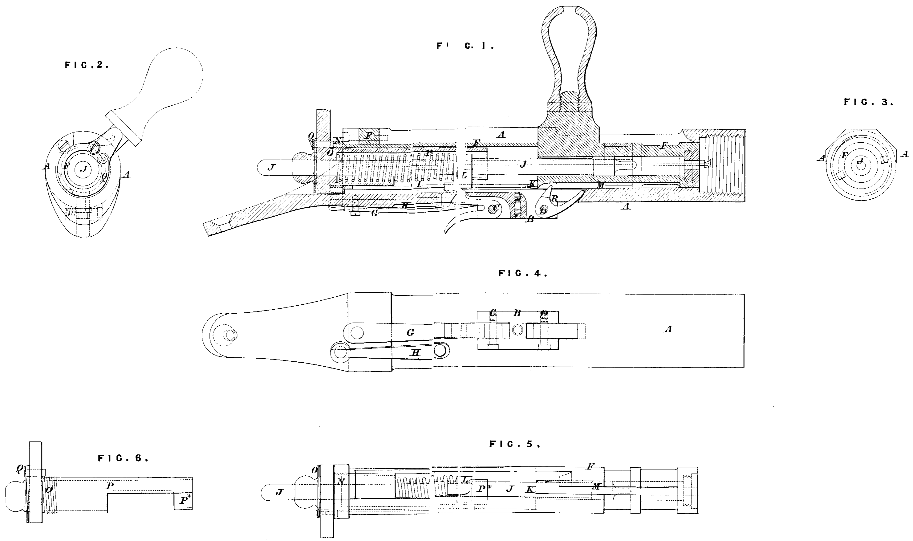
Fig. 1 is a longitudinal section of the shoe or breech piece, shewing the plunger drawn back but not pulled down into its position of being locked for firing; Fig. 2 shews the rear end of the breech piece, and Fig. 3 the front end of the same; Fig. 4 is an underneath plan of the breech piece; Fig. 5 is a similar view of the plunger; Fig. 6 represents the elongated screw or retainer for the striking pin detached. In these several Figures the same letters of reference indicate corresponding parts.
A is the shoe or breech piece with a block B on its under side, in which is inserted the fulcrum C of the sear connected with the trigger, and also the fulcrum D of the thrower, which block serves also as a means of fixing the breech piece to the stock by a screw ; E is a stop for the plunger F, jointed to the top of the breech piece, which stop is snapped into its place by a spring, and can be lifted up for the removal of the plunger as required ; G is a spring to act upon the sear; H is another spring to act on the riin formed on the end of the plunger ; I is a slot in the hollow of the plunger along which the striking pin J is enabled to work freely; K is an inclined plane for the stud or block L of the striking pin to act against in order to prevent the discharge of the gun before the plunger is turned into its position for firing. By the form of the slot represented the striking pin and spiral spring may be removed by the fingers only. M is a groove -formed in the under side of the plunger, which is widened to admit of the handle being turned down without coming in contact with the short arm of the thrower; N is a screw formed at the rear end of the plunger, in which is screwed the guide or closer 0, which is formed with a tube P, a portion thereof being removed to form a hook or retainer P* for the striking pin; Q, is a spring to act upon a stud in order to retain the screw N in its required position; R is the thrower for throwing out the cartridge case, having its fulcrum at D; the short arm of this thrower passes along the groove M in the under side of the plunger until it comes in contact with the end of the same, when it is drawn back and the long arm throwp upwards so as to throw out the cartridge case.
The action of the gun is as follows :—Assuming that a cartri^go has been inserted in the breech there are only two mechanical motions required for loading and firing the gun. The cartridge is pushed into its proper place and the striking pin drawn back for firing by the operation of closing the breech, and the empty cartridge case is withdrawn and thrown out of the breech by the operation of opening the breech. The block B of the shoe or breech piece A is lengthened for the purpose of carrying the fulcra of the sear and thrower to suit the present modification of the same, and is fixed to the stock and connected with the guard by means of screw pins, as in my former Patent. By this arrangement the breech piece, the plunger, and the stop for the latter can be made shorter than by the arrangement in my former Patent. The guide or closer 0 enables the gun to be carried with safety when loaded by merely turning the projection formed on it towards the left hand, thereby bringing the hook P* at the end of the tube P in front of the stud or block L of the striking pin. When the projection is turned towards the right hand the gun can be fired without any impediment to the action of the striking pin. After the cartridge case has been withdrawn by the extractor the long arm of the thrower R is thrown upwards by the short arm thereof coming in contact with the solid part of the plunger at the end of the groove M in the under side thereof when the pluuger is drawn backwards for reloading.
Having thus described the nature of the said Invention, and in what manner the same is to be performed, I would remark that I do not claim under this present Patent any of the parts above referred to which are contained in my former Patents ; but what I do claim as of my Invention under the above in part recited Letters Patent is,—
First, the elongated screw for closing the rear end of the plunger formed so as to be capable of acting as a safety hook or stop for the striking pin.
Secondly, the thrower acting in connection with the plunger, as represented and described.
And, lastly, the combination of the elongated screw and thrower with the breech piece and plunger modified to suit the same.
In witness whereof, I, the said William Tranter, have hereunto set my hand and seal, the Thirtieth day of January, in the year of our Lord One thousand eight hundred and sixty-eight.
WILLIAM TRANTER. (l.s.)
Witness,
William Spence,
8, Quality Court,
Chancery Lane,
London, W.C.