
British 1694
Spring loaded repeating revolver
LETTERS PATENT to William Edward Newton, of the Office for Patents, 66, Chancery Lane, in the County of Middlesex, Civil Engineer, for the Invention of “Improvements nr the Construction op Repeating Firearms.”—A communication.
Sealed the 20th October 1854, and dated the 1st August 1854.
PROVISIONAL SPECIFICATION left by tbe said William Edward Newton at tbe Office of tbe Commissioners of Patents, with bis Petition, on tbe 1st August 1854.
I, William Edward Newton, of tbe Office for Patents, 66, Chancery Lane, in tbe County of Middlesex, Civil Engineer, do hereby declare tbe nature of tbe said Invention for “ Improvements in the Construction op Repeating Fire-arms ” to be as follows:—
This Invention consists, first, in providing a reservoir of power capable of discharging two or more chambers or barrels in succession.
Second, in effecting tbe explosion of tbe cap or other percussion priming by tbe motion of tbe chamber in revolving, & thus causing tbe said revolving chambers to perform tbe function of tbe ordinary hammer or cock.
Third, in the application to repeating fire-arms of an escapement or escapements, similar to those used in time-pieces, for’ tbe purpose of exhausting at intervals a reservoir of power obtained by tbe compression of a spring or springs, or their equivalents, and which will discharge two or more chambers or barrels successively.
Fourth, in so hinging the barrel or frame which supports it to the stock, that when the said barrel is swung back or forward, either for charging the fire-arm or otherwise, it will contract or compress a spring, or supply a reservoir of power capable of discharging two or more barrels or chambers successively, without re-cocking or re-charging the reservoir.
Instead of effecting the compression of the spring by the movement of the barrel or frame upon its hinge, as described, this operation may be effected by turning a hand piece or the stock of the fire-arm.
SPECIFICATION in pursuance of the conditions of the Letters Patent, filed by the said William Edward Newton in the Great Seal Patent Office on the 1st February 1855.
TO ALL TO WHOM THESE PRESENTS SHALL COME, I, William Edward Newton, of the Office for Patents, 66, Chancery Lane, in the County of Middlesex, Civil Engineer, send greeting.
WHEREAS Her most Excellent Majesty Queen Victoria, by Her Letters Patent, bearing date the First day of August, in the year of our Lord One thousand eight hundred and fifty-four, in the eighteenth year of Her reign, did, for Herself, Her heirs and successors, give and grant unto me, the said William Edward Newton, Her special license that I, the said William Edward Newton, my executors, administrators, and assigns, or such others as I, the said William Edward Newton, my executors, administrators, and assigns, should at any time agree with, and no others, from time to time and at all times thereafter during the term therein expressed, should and lawfully might make, use, exercise, and vend, within the United Kingdom of Great Britain and Ireland, the Channel Islands, and Isle of Man, an Invention for “Improvements in the Construction of Repeating Fire-arms,” being a communication from abroad, upon the condition (amongst others) that I, the said William Edward Newton, by an instrument in writing under my hand and seal, should particularly describe and ascertain the nature of the said Invention, and in what manner the same was to be performed, and cause the same to be filed in the Great Seal Patent Office within six calendar months next and immediately after the date of the said Letters Patent.
NOW KNOW YE, that I, the said William Edward Newton, do hereby declare the nature of the said Invention, and in what manner the same is to be performed, to be particularly described and ascertained in and by the following statement, reference being had to the Drawings hereunto annexed, and to the letters and figures marked thereon (that is to say):—
This Invention consists, first, in providing repeating fire-arms with a reserve of motive power which shall be capable of effecting the discharge of two or more charges of powder in succession without the said power being required to be renewed.
Second, in causing the explosion of the caps or other percussion priming by the rotary motion of the breech cylinder, in which case the breech cylinder performs the function of the ordinary hammer or cock.
Third, in the application to repeating fire-arms of an escapement or escapements, for the purpose of exhausting the store of power obtained for the purpose of discharging the fire-arm.
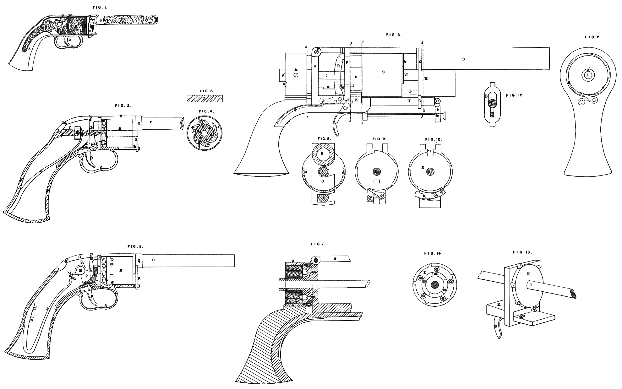
In the accompanying Drawings, Fig. 1 represents in perspective view a pistol constructed according to this Invention; Fig. 2 is a side view of the pistol upon an enlarged scale, with the cheeks of the stock removed, to shew the internal construction; and Figures 3 and 4 represent views of detached portions thereof. Similar letters in the several Figures denote like parts.
In Fig. 1, A represents the stock of the pistol; B is the revolving breech cylinder, containing the chambers for receiving the charges; C is the barrel; D is the trigger; and E is the latch or catch which holds the barrel and breech cylinder securely in their places when the pistol is ready for discharging. The unhooking of this catch permits of the swinging or raising up of the barrel, to remove the revolving cylinder, or the charging of it after the chambers have been discharged. It will be perceived by this Figure that there is no projection on the upper part of the pistol in the least to obstruct the aim, that the caps are exploded under such protection as to prevent any danger of their fragments flying into the face of the user, and that the compact form of the pistol admits of its being conveniently carried.
In Fig. 2, F represents the skeleton of the stock. The barrel C is firmly connected to the frame G, which extends rearwards, and is hinged or pivoted to the stock at a. The extreme rear portion of the frame G behind the pivot is provided with a cam projection h, which, as the barrel and frame is swung back, comes in contact with a threaded nut H, which is supported by and runs upon a screw shaft I. The threads of these screws should be cut “ long,” as it is mechanically termed, that is, at an angle of about forty-five degrees (more or less), so that by pressing against either the nut or screw shaft in a direct line, one will turn the other without the operator actually turning (as in an ordinary screw) the first moving piece. When the cam projection l strikes the nut H, by still further swinging back the barrel and frame, the nut H (which is prevented from turning round, by moving between guides or guide pins in it, projecting into suitable grooves or slots,) is driven along on the screw shaft or rod I (the screw shaft turning to permit of this movement), and at the same time a main spring J, suitably arranged and attached to the stock, is compressed by the traverse of the nut; the object of the spring J being merely to form a reservoir of power, which will, by successive or periodical releasement, discharge a series of chambers as they are in succession brought round opposite the barrel; it will be readily understood that many equivalents might be substituted therefor, without departing from the nature of the present Invention. The shaft I turns on a journal on its rear end, which is suitably supported in the frame G, and on this shaft is firmly attached a wheel, the teeth of which are seen at c, in Fig. 5, there being a tooth for each chamber in the revolving breech. The shaft I forms the arbor for the revolving cylinder B, and it projects far enough beyond the front of the revolving chambers to allow the catch or latch E (as shewn in Fig. 1) to embrace it, and thereby hold the cylinder and frame firmly together. A pin e, shewn by dotted lines in Figures 2 and 4, is placed in the toothed wheel projecting forwards, and this pin enters a corresponding hole in the rear of the revolving chambers or breech piece when it is slipped on to the spindle, which causes said chambers or breech to revolve with the toothed wheel and shaft I, and is a permanent guide for the slipping on of the revolving breech, so as to bring the nipples 1, 2, 3, &c. in a proper position to conform to the other moving parts of the pistol.
An anchor escapement, or three-armed lever L, is so arranged as gradually or at stated periods to exhaust the spring J, causing it to rotate the cylinder B, explode the cap or priming as the chambers come successively round opposite the barrel, and restrain the spring when not required to discharge the piece. One of the arms f of the escapement projects through a slot in the division plate N, and comes in the line of rotation of the nipples, and each cap as it comes round with its nipple is exploded against the said arm, the force of the blow against the arm being taken off by the arm resting against the division plate through which it projects, whilst it affords a firm rigid bed for the cap to strike against. The nipples should with their caps revolve just near enough to a guard plate to turn freely, and yet prevent the caps from being thrown off from their nipples by their motion in revolving, or the jar in exploding; and in advance of where they are exploded may be provided an opening in the guard plate, through which a cap may be replaced should one fail to explode. Another arm i of the escapement lever projects through the division plate N at the lower side of the pistol, which arm i, as it is alternately thrown up and down by the action of the trigger, (and a spring, to be hereafter described,) catches, and anchors or releases the toothed wheel, and with it the cylinder, which is attached to it by the pin e. It will be perceived that when the arm i releases the toothed wheel, the arm / is by the same movement thrown into position for arresting the first cap which comes round, and thereby causing its explosion. The third arm of the escapement is seen at n. This arm projects rearward (the other two projecting forward), and is operated upon by a spring 0, which should have sufficient power after the trigger D is released to pull back the arm/, and by the same motion throw up the arm i, to prevent the further rotation of the breech cylinder until the trigger is again pulled. The movement of the trigger raises up the arm n, throws forward the arm / releases the arm i from the toothed wheel, and another discharge is caused, and so on, until the spring J is exhausted, or all the barrels are discharged. When this is the case the fire-arm must be re-loaded and re-cocked for the next round of discharges.
It might possibly appear that a very powerful spring would be required, which by one contraction should be capable of effecting six discharges (the capacity of the pistol just described being equal to receive six charges); but such is not the case, for the spring is only required to cause one entire revolution of the breech chambers to discharge them all. It is true that the momentum is lost at every discharge, and that the spring becomes weaker at each discharge, but in practice no difficulty has been found in making six discharges with one setting of the spring or springs, which may compose the reservoir of power. In order to maintain as nearly as possible an equable pressure of the spring, so as to perform the last portion of the rotation with about the same force as the first, the speed of the thread of the shaft I may be graduated, as shewn at Fig. 3, the inclination being greater as the spring exhausts, so as to present less resistance to it. If this plan is adopted, then, instead of an entire thread in the nut, which of course would not run on a variable screw, the nut should be provided with a few small steel points, just sufficient to rotate the shaft and the breech cylinder which it carries. As another method of accomplishing the above-named object, an auxiliary spring, which can be set by the same action or at the same time with the main spring, may be used and brought into action as the main spring begins to exhaust.
Fig. 5 shews a modification of the Invention. In this case the barrel and frame to which it is attached is the same as in Figures 1 and 2; but the cam projection b of the frame G, instead of running a nut forward on a screw shaft, and contracting a spring for furnishing a store of power for repeated discharges, comes in contact with the cam r, on a square shaft s, which shaft also carries another cam £, to which the main spring J is connected by a link u; on -this shaft s is also arranged a segmental rack o, which works into a bevil wheel P, on the arbor of the breech cylinder. The escapement L exhausts the spring J, in the manner described with reference to Figures 1 and 2, but the axial motion of the rotating breech cylinder is transmitted through the segment rack and pinion 0, P, instead of through the nut and rod. The cap is exploded in the same manner against the arm/, and the arm i may either operate, as in the before-described plan, or without the toothed wheel, as shewn in the Figure. In this case the arm extends forward to the breech cylinder, and the end, being turned up, catches into a ring of wedge-shaped or inclined depressions a?, formed in the periphery of the cylinder, and thus locks the cylinder, as in the former arrangement. The escapement in both examples is pivoted at v, and instead of a trigger separate from the escapement, a prolongation of the escapement may be made, which will serve the purpose of a trigger, and still further simplify the fire-arm. A stop or bolt w, consisting of a pin in the frame or stock, may be moved into a slot in the top of the escapement, for securing the fire-arm against accidental discharge. The latch or catch E for holding the barrel and breech cylinder firmly together depends from a collar Q, which surrounds the barrel, and it is provided with a suitable slot for holding fast to the breech arbor, and also with a slot for catching over the piece R, which forms the lower part of the frame of the fire-arm to which the guard s is attached.
The small holes in the sectional part, Fig. 4, represent the communicating passages between the nipples and the chambers. The nipples themselves are set tangentially upon the revolving cylinder, or so inclined or curved as to bring their respective caps square up against the arm f to ensure their explosion.
The operation of this fire-arm will be clearly understood from the Drawing and description, and its peculiar advantage over others may be clearly seen. To charge and cock it for six discharges requires no more time or trouble than any other repeating fire-arm. To discharge it requires but a slight touch of the trigger, for it may be a hair trigger, if desired, whilst a steady sight may be kept on the object fired at all the time. The arm need not be lowered, and no exertion of the muscles of the arm exercised in cocking or revolving the chambers; a slight touch of the trigger lets off each successive charge. On the first discharge, this fire-arm would display no peculiar advantage over other repeating fire-arms on the discharge of their first barrel, but after that period the remaining five charges (if the Invention be applied to a six-chambered pistol) could be fired before the second chamber of an ordinary repeating firearm could be discharged, holding in view the fact that proper aim or sight is to be taken, and with a precision due only to this construction, as it does not require the arm of the user to be lowered or contracted or any effort of the muscles to cock or rotate the breech cylinder, which effort more or less destroys a perfect aim by causing the arm to becomes nervous, and by the difficulty in cocking and rotating at each discharge.
A further modification of this Invention is shewn, as applied to a pistol, at Figures 6 and 7, the former of which is a side view of the pistol, and the latter a partial longitudinal section of the same. Detached views of this arrangement are also shewn; Fig. 8 being a cross section through the line 2,2, of Fig. 6; Fig. 9, an end view at the line 3, 3, of Fig. 6, looking to the right; Fig. 10, an end view at the line 4, 4, of Fig. 6, looking to the left; Fig. 11, a rear view of the stock and spring box; and Fig. 12, a rear view of the cock or hammer.
Similar letters, where they occur in the several Figures, denote like parts.
A represents a spring box for containing a coiled spring (shown in section at Fig. 7); B, the barrel; C, the rotating chambered breech; D, the hammer; E, the rotating toothed scape wheel; F, the trigger; G, the latch or catch which holds the breech and barrel securely to the frame, and in their places when the pistol is ready for being discharged; S, in dotted lines, is the spring for operating or throwing forward the hammer after it has been set or cocked.
The barrel B is securely fastened to the swinging frame H, which extends rearwards and is hinged to the rear division plate 0 at a, and when in its proper position it is secured therein by a catch G, as in the former examples; M is a guard (to be hereafter described) connected to the catch G, so that when the fire-arm is to be recharged it can be swung with the latch entirely out of the way of the ramrod. The guard may be detachable, as it is only important when one hand and arm is advanced to support the front of the fire-arm, as in rifles or shot guns, or when taking deliberate aim with a pistol.
J is the ramrod, slotted and connected to a hinged arm b, by a pin b1 passing through it. This arrangement will admit of the ramrod being drawn out, reversed, and used for ramming hoine the charges, and then returned to its place without being at any time detached from the fire-arm.
The breech cylinder arbor I extends rearwards into and through the spring box A, and has upon that portion of it within the spring box a hook or catch, for bolding one end of the coiled spring contained therein, or for the more readily facilitating of the taking apart of the arm. The end of the shaft or arbor I is passed through a sleeve c\ Fig. 7, and connected thereto by a pin c11, Fig. 6, so that they will turn together. This sleeve c1 serves as an arbor, around which the spring is wound or compressed by the operation of turning the stock, and upon this sleeve the hook or catch for holding one end of the spring may be placed. The shaft I projects through the rear division plate O and through the hammer D (Fig. 12), and serves as a guide for the movement of the hammer. It passes also through the front division plate P and the toothed “ scape wheel ” E, which latter is connected to and moves with the shaft. This connection may be made by a slot in the “ scape wheel” and a feather on the shaft I, in a manner well known to mechanicians. The slot and feather may also serve as a guide for putting together the parts, always relatively, in the same position. The nipples which are on the rear of the cylinder C extend through the “scape wheel ” E, as shewn in the detached view, Fig. 14, and the said “ scape wheel ” protects them from injury of any kind. At each periodical releasement of the wheel E and coiled spring in the box A, by the operation of the trigger F and the anchor K, the wheel and breech cylinder C are caused to rotate, and to present the nipples severally and in succession opposite the hammer D, which hammer is by the periodical release of the coiled spring turning the shaft I simultaneously tripped by the action of the trigger on the anchor K.
The trigger F is pivoted at/, and acts against a bolt/1, which passes into the anchor K, so that by the drawing of the trigger backward it will raise up one end of the anchor K (see Fig. 10), causing that end to catch into or against one of the teeth or projections of the toothed wheel E, and throw out the other end of the anchor, which previously held the wheel, thus allowing the wheel and breech cylinder connected to make a portion of a revolution, and be again caught when the trigger releases the bolt /1; the spring il under the anchor will then again throw up the other end thereof and again catch the heel, and so on, until all the chambers are discharged, or the spring or reserve of power exhausted.
Many modifications for letting out the spring might be adopted, if thought desirable; for example, the one represented in Fig. 13 avoids the necessity of a spring to throw up the anchor, and removes all or any objection that might arise as to the uncertainty of tho before-described plan, for as the spring becomes weakened, or if it should break, the chambers might revolve more than their allotted distance. The contrivance, represented at Fig. 13, may be called “a dead beat escapement,*’ or one working with a positive effect, making it impossible for the cylinder to turn any farther than the desired and given distance. In this Figure, E may represent the “ scape wheelI, the breech cylinder shaft or arbor; and F, the trigger, which may be a permanent part of a sliding piece K, having two teeth k\ kx\ so arranged, that as one kl is slidden into the circuit of the “ scape wheel,” the other k11 will be out of that circuit, and vice versa. It will be thus seen that it is impossible for the wheel to turn farther than its given distance, as the act of drawing out of the way one of the teeth, to allow it to move at all, draws the other one in the precise spot for catching the first tooth that comes round on the “ scape wheel.” Instead of the bolt/1 (as represented in Fig. 6) being a separate piece from the trigger, it may be a part of the trigger itself, and release and catch the “ scape wheel,” as it (the “ scape wheel ”) turns by the uncoiling of the spring. If considered essential to guard against the breaking of the spring which works the anchor, a ring trigger may be used, and the anchor worked from the trigger, regardless of the spring, as the moving of the trigger forward and back by the forefinger in the ring will operate the anchor.
In Fig. 6, L represents a brace, which is a part of or connected to the latch G, and bears against the face of the rotating breech cylinder, for the purpose of preventing friction between it and the end of the barrel at h, and to cause it to turn true on the arbor I.
To secure the handle or stock of the fire-arm in such a manner that it may be easily turned to admit of winding-up or compressing the spring, and yet not shake or work loosely, the bearings or connections are constructed in such a manner as to allow of the handle turning freely, and yet of the whole fire-arm remaining firm in the hand of the user, i, i, (Fig. 7) represents in section a conical ring, which is fastened firmly to the box A, by screws or otherwise; and //represents a circular conical plate, fitting exactly into the riugi,?, and fastened to the rear division plate 0 by screws, which pass through the closed end of the spring box; a bearing is thus made, at once both simple in construction and strong, and allowing the handle and spring box to be turned upon the frame with great readiness.
The click, by which the spring in its box is held compressed, after having been wound up, as before described, by turning the handle, maybe arranged, as seen in Fig. 9, with a corresponding bolt or catch, which takes into the several teeth of the ratchet wheel, and thus holds the spring.
A bolt, such as is used on many other repeating fire-arms, may be used on this one, so that the action of the fire-arm may be withheld; or to prevent any accidental discharge, by jarring, falling, or other similar mishap, which is incidental to the use of all fire-arms, it may be so arranged as to pass between the “ scape wheel ” and anchor, so as to prevent any forward motion of the anchor; this would.be as simple and effective an application of the bolt as any other, as to check or fasten the anchor locks all the working parts of the fire-arm.
In loading this arm, after, the catch G is raised up, the cylinder C and “scape wheel ” E are slipped forward on the spindle just far enough to release the “■ scape wheel ” from the anchor, and then the cylinder is free to be turned to meet the ramrod J and be charged. Whilst the cylinder with its “scape wheel ” is thus run forward the nipples can be capped, and when returned the latch or catch put down, and the handle turned to coil the spring, the fire-arm is ready for firing a series of charges.
On the rear of the “scape wheel ” E, as seen in Fig. 14, (which is a section taken at the line 9, 9,) is a series of cam planes m, corresponding to the number of chambers in the revolving breech. Against these planes the end of a bolt n (Fig. 6) works, as follows:—When the breech cylinder is released, by means of the anchor and trigger, the cylinder in turning brings one of the planes m against the bolt «, and drives a shoulder o on the said bolt against the hammer D, and thereby pushes back or cocks the hammer. In the act of cocking, the hammer compresses a spring qy the extremity of which presses against the arm p of the hammer, and in this position the arm stands after each discharge, it being caught by the anchor and escapement. Now, by pressing upon the trigger the anchor is released, the “ escape wheel ” makes another partial rotation, bringing the nipple to the exact spot for receiving the blow of the hammer, and simultaneously letting oft’ the hammer, which carries forward with it the bolt n, for the repeating the discharge. It is, therefore, (when the arm is once loaded and the reserve of power obtained) but the simple act of pressing the trigger, (which may be a hair trigger, if desired,) that cocks, rotates, and discharges the fire-arm, so that the aim may be preserved, and the whole series of discharges let off, without taking down the arm, and that with but a slight touch of the finger.
It may be found in winding up the spring within the box A, or when, for instance, it is only partially wound up, that the stock is not in exact line with the barrel. To avoid this, a ratchet and pawle may be used, which, when the handle or stock is turned in the direction for winding up the spring, will act together and hold, but which, should the handle not be in exact line after the spring is, wound up as far as it will go or be required, may be turned back far enough to bring it in line without letting out any part of the spring, as that is caught and held by another click, as described, with reference to Fig. 5. The guard M is so constructed as to allow an accidental discharge of any of the chambers to escape without striking against any part of the weapon or endangering the hand of the user.
It will be understood that the main features of this Invention are equally applicable to fire-arms constructed with rotating barrels as with a rotating breech cylinder.
Having thus set forth the nature of the Invention of “ Improvements in the Construction of Repeating Fire-arms,” as communicated to me by my foreign correspondent, and explained the manner of carrying the same into effect, I wish it to be understood that under the above in part recited Letters Patent I claim,—
First, the application to repeating fire-arms of suitable mechanism, as above explained, for obtaining a reserve or stored-up power, for the purpose of rotating the breech cylinder and cocking or releasing the hammer, or its equivalent, in concert, so as to produce two or more discharges in succession without a renewal of the motive power being required.
Secondly, the mode of giving out the stored power by intermittent impulses, as herein-before described.
Thirdly, so combining the stock with the frame, that by rocking the frame on its hinge, by turning the stock, a spring or springs shall be compressed or wound up which shall be capable of actuating the fire-arm for a series of discharges, substantially as described.
In witness whereof, I, the said William Edward Newton, have hereunto set my hand and seal, the First day of February, in the year of our Lord One thousand eight hundred and fifty-five.
W. E. NEWTON, (l.s.)
Witness,
J. W. Moffatt, i 66, Chancery Lane.