
British 2297
AD. 1854 № 2297.
Revolving-breech Fire-arms.
LETTERS PATENT to Edward Lindner, of the City and State of New York, in the United States of America, for the Invention of “Improvements In Revolving-Breech Fire-arms and Magazine.”
Sealed the 24th April 1855, and dated the 28th October 1854.
PROVISIONAL SPECIFICATION left by the said Edward Lindner at the Office of the Commissioners of Patents, with his Petition, on the 28th October 1854.
I, Edward Lindner, of the City of New York,in the United States of America, do hereby declare the nature of the said Invention for “Improvements In Revolving-Breech Fire-arms and Magazine” to be as follows:—
I construct my fire-arm with one barrel, either rifled or plain, and attach a chambered breech in an opening behind the barrel, so that the upper chamber in said breech shall coincide with the bore of the gun. This chambered breech is fitted so that it can be revolved on a pipe, within which pipe is a sliding rod receiving its motion from the cock or hammer; so that as the hammer is cocked, a latch.on said rod (moving in a slot.in the pipe on which the chamber revolves) takes one of a series of spiral grooves around on the inside of the centre hole of said chambered breech, revolving the same sufficient to bring the next chamber on the line of the barrel. The centre rod is prolonged through beneath the barrel, and fitted with guides, that allow the same to slide endwise, and said rod passes between the barrel and a pipe that contains cartridges; and a follower in said pipe, taken by latches on said sliding rod, forces each cartridge in succession back into the lower chamber of the revolving breech, whence it is brought around to be fired in turn. In order to explode the cartridge as it comes on to the line of the barrel (in consequence of cocking the piece as before described), I use a needle, set and moving in slides, with a circular spring around it, and the back end of the needle projecting through. The cock is moved by the main spring,and discharged by the trigger as usual; but instead of the end striking a cap, as usual, I fit a small latch, to move on a centre crosswise of the hammer, which as the hammer is discharged, takes the rear end of the needle, forcing the same into the cartridge, exploding a percussion pill contained in said cartridge, and a fixed cam lifts the end of this latch as the needle gets fully home, allowing the said needle to be thrown back by its spring, so as not to get heated by the explosion.
In order to use caps when desired with this fire-arm, I fill an annular groove with said percussion caps, and have the same so attached to the gun that the end cap in said ring is on the line of the nipple and barrel, and as the slide which is attached to the hammer comes up on firing the piece, it carries said cap out of the ring on to the nipple, and explodes the same, firing the piece. Two, three, or more tubes containing cartridges may be applied beneath and around the barrel, each of which has its cartridges emptied successively into the breech as the same is revolved by firing the piece, and a cartridge box may be constructed of a series of tubes to be emptied into said pipes to replenish the same. My claims are, to the means for rotating the chambered breech; to the means for supplying cartridges to the rotating breech out of a pipe or pipes; to the means for firing said cartridge when on the line of the barrel by he needle, actuated as described, or by percussion caps, as specified; also to a cartridge box of pipes to supply those attached to the barrel; and also to a knife in the inside of each chamber to pierce and cut the end of the cartridge, so that it can be exploded; and to a peculiar rammer which may be used to force home the ball into the chamber.
SPECIFICATION in pursuance of the conditions of the Letters Patent, filed by the said Edward Lindner in the Great Seal Patent Office on the 28th April 1855.
TO ALL TO WHOM THESE PRESENTS SHALL COME, I, Edward Lindner, of the City add State of New York, in the United States of America, send greeting.
WHEREAS Her most Excellent Majesty Queen Victoria, by Her Letters Patent, bearing date the Twenty-eighth day of October, in the year of our Lord One thousand eight hundred and fifty-four, in the eighteenth year of Her reign, did, for Herself, Her heirs and successors, give and grant unto
me, the said Edward Lindner, Her special licence that I, the said Edward Lindner, my executors, administrators, and assigns, or such others as I, the said Edward Lindner, my executors, administrators, and assigns, should at any time agree with, and no_others, from time to time and at all times thereafter during the term therein expressed, should and lawfully might make, use, exercise, and vend, within the United Kingdom of Great Britain and Ireland, the Channel Islands, and Isle of Man, an Invention for “Improvements In Revolving-Breech Fire-arms and Magazine.” upon the condition (amongst others) that I, the said Edward Lindner, by an instrument in writing under my hand and seal, should particularly describe and ascertain the nature of the said Invention, and in what manner the same was to be performed, and cause the same to be filed in the Great Seal Patent Office within six calendar months next and immediately after the date of the said Letters Patent.
NOW KNOW YE, that I, the said Edward Lindner, do hereby declare the nature of my said Invention, and in what manner the same is to be performed, to be particularly described and ascertained in and by the following statement thereof, reference being had to. the Drawings hereunto annexed, that is to say:—
The nature of my Invention consists in providing below the gun barrel an extra charge barrel, which. according to-its-length contains from thirty to fifty cartridges. Between the gun and charge barrel is a rack, in connection with a piston or slide, which acts upon the cartridges, and which said rack is again in connection with the gun lock, in such a manner, that each time the gun is fired off, one of the cartridges is forced into a revolving breech piece, by which mean he whole amount of cartridges contained in the charge barrel can be fired off in the shortest possible time. The revolving breech piece is turned round each time the gun is cocked one-sixth part by a mechanism applied to the inside of the same. The percussion caps are brought exactly opposite the nipple by an arrangement of springs, and are put on the same by the hammer itself at the moment the gun is fired off, while the fired-off caps are thrown oft’ from the nipple when the gin is cocked. The needle lock is so arranged, that the needle, after having entered the cartridge sufficiently far to ignite the priming, springs suddenly back, by which arrangement any heating of the needle is effectually prevented, and the application of a revolving breech piece is permitted.
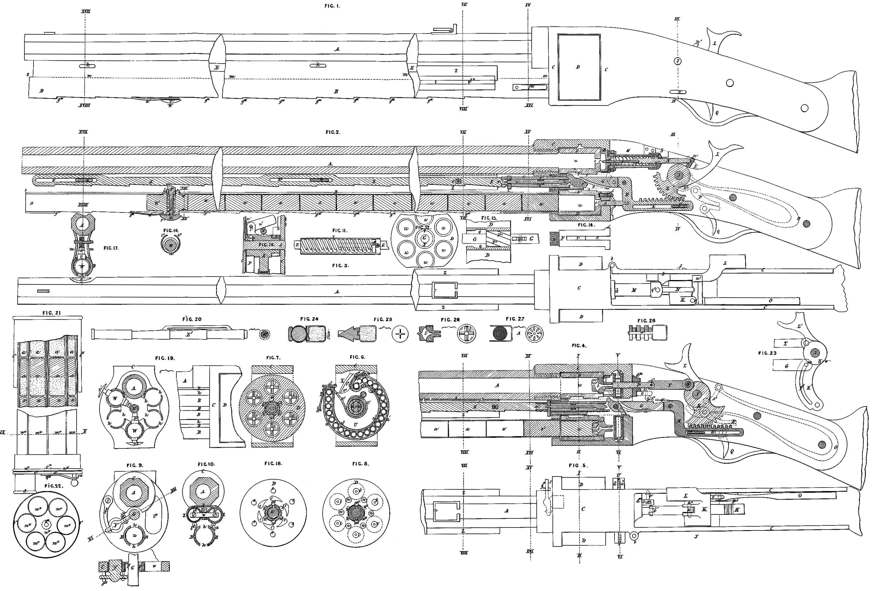
Figure 1 of the Drawings annexed is an outside view of the gun; Figure 2 is a longitudinal section of the gun adapted to the needle lock; Figure 8 is an outside view of the same; Figure 4 is a longitudinal section of a gun with the percussion-cap lock; Figure 5 is a top view of the same, shewing the ramming hammer; Figure 19 is a cross section and part of a side view of a gun or pistol with five charge barrels; Figure 20 is a view of a round rack for guns or pistols where several charge barrels are used; Figure 21 is a section and outside view of a cartridge box particularly adapted to this gun. All other Figures are views and sections of several parts of this gun, &c., and will be more particularly mentioned in the following description:— A is the barrel of the gun, which is screwed to the frame C at its after end in such a manner that its bore corresponds exactly with the openings in the revolving breech piece D. B is the cartridge or charge barrel, which is likewise fastened to the frame C. The same is made of very thin metal, and is provided with two slots k, k, (Figures 9, 10, 19,) running very nearly the whole length, and in which the slide or feeder W is guided. On the lower side of this barrel are cut teeth of the same number and distance apart as the teeth on the rack IE. The two barrels A and B are connected together by the side plates m, m, (Figure 17,) between which the rack I is situated, provision being made in the plates m, m, for the flat keys k, k, by which the rack E is guided (Figure 2). C is the frame to which the barrels are attached, and within which the revolving breech piece, the gun lock, springs, &c. are situated, (Figures 1, 2, 8, 4, and 5.) If made for the percussion-cap lock, the same is provided with two projections c”’, This frame has two prolonged sides, by which the whole is fastened with screws to the wooden butt end of the gun. One of these side plates is made with a joint b, for the purpose of facilitating access to the lock. D is the revolving breech piece, provided with six holes u, u, u, and ground into the frame C perfectly tight. Tor the needle lock, (Figures 12, 18,) the holes u are not quite bored through, and are somewhat countersunk towards the gun barrel, and smaller holes arc at the back bored through to allow a free entrance for the needle, as shewn at e, e, e,e, (Figure 18). At the after side are likewise six tapering recesses c, in which the pin d, provided with a spring, fits, (Figure 2,) and by which the revolving breech piece I) is held fast in one position: On the knee piece H is firmly attached a stop pin g, which enters the lower hole e of the breech piece D, holding the same stationary while the needle enters the upper hole e in the same to discharge the gun. The revolving breech piece D; adapted for the percussion-cap lock is represented in Figures 4, 7, and 8. Figure 7 shews a section on the line I. and II. of Figure 4; and Figure 8 is a back view of the same. l, l, l, l, l, l, are six nipples (Figure 26), screwed into the back end of the same (Figure 4). n, n, n, are recesses, into which the stop pin o (Figures 4 and 5) fits, to hold the breech piece in its position. In the centre of the breech piece a hole is bored out (Figure 18), in which six spiral grooves p’ are cut, for the purpose of turning the breech piece from the inside by means of the piece p (Figures 2, 4, 13). q (Figure 183) is a recess, sharply turned in, where the grooves p’ terminate, for the purpose of allowing the piece p to drop after having passed through the spiral grooves p’. Tis a hollow pin screwed in the frame.C, and upon which the revolving breech piece is carried and allowed to turn. The same is bored out sufficiently large to allow the piece G to pass through it easily, and is provided with two slots r and s (Figure 14), large enough to allow the piece p to move in the same. E is the rack (Figure 24), situated between the gun barrel A and the cartridge barrel B. This rack has the same number of teeth as the number of charges for which the cartridge barrel is arranged, and these teeth are exactly the same length or distance apart as the length of one cartridge. Towards the middle and near the forward end is made a slot K’, in which the key K is fitted, and through which the rack E is guided. v is a square hole, through which the square bolt w passes, and which through the motion of the rack is carried back and forward with the same. To the after end of the rack E is attached the round rod G, which passes through the bolt F, as before described, In this rod G is let in the piece p, so that the same can move around a pin fast through G, and the end is bored out from the rack IX up to the point where the piece p is attached. Behind the piece p is a spring, which is let into the rod G in such a manner that it presses upon the lower projection of the piece p, thereby forcing the same always upwards. In the bored-out part of the rod G is a turned rod z, provided with a small spiral spring. The after end of this rod fits into the recesses of the piece p, and the forward end is, provided with a cross pin z’, which is held fast during part of the time the rack E with the. rod G is moving, and thereby compresses the spiral spring around the rod z, so as to give the latter a small motion when released. On the after end of the rod G is attached the knee piece H, having teeth cut on it, and provided with a slot h’, into which the key c’ is fitted, and by which it is guided and made to move parallel when moved by the segment K. W is the feeder, which slides in the cartridge barrel (Figures 2, 16, 17, and 19), and is made to press upon the charges by the rack E. The feeder is made round to fit into the cartridge barrel, with flat projecting pieces 1 and 2, which fit into the slots h, h, of the same, and by which the piston is guided. Through these projecting pieces 1 and 2 the pin s’ passes, the upper end of which fits the teeth of the rack E, and the lower end receives a small head r’. The pin s’ is provided with a spiral spring, to press the same always against the rack E and into the teeth. To prevent the piston from moving while the rack E makes the backward motion, a small spring a! is attached to the head r’, which falls into the teeth made at the lower side of the cartridge barrel B. Figure 16 represents a section at the lines XIII. and XIV. of the piston W, shewing a. small spring t’, which is placed around the groove of the piston, Figure 2; for the purpose of keeping the same steady in the cartridge barrel B. Figure 17 represents a section at the lines XV. and XVI., shewing the gun barrel A, the cartridge barrel B, the feeder W, in connection with the rack E, as well as the connecting side plates m, m, and key K, by which latter the rack E is guided, as has before been described. K is a segment fast on the pin J, Figures 2, 8, 4, and 5,) and by which the knee piece H is worked. Upon the pin J is fastened the cock L. On the segment K is attached the link o’, through which a communication is made with the same, and consequently with the cock L and the main spring O, as well as with the catch P and the notch W’, when the gun is cocked. Q is the trigger for firing off the gun; M is the needle box, screwed to the frame C, and in which the needle f with the needle carrier N moves and is guided; this box has a cover g’, screwed on, for the purpose of putting in or taking out the needle and carrier. The needle carrier has a collar a”’, against which a spiral spring acts; the other end of which spring presses against the box R in such a manner as to keep the needle with the carrier always out of the revolving breech piece D except when forced in by the action of the hammer L. R is an air box, fitted tight against the back face of the revolving breech piece D, and pressed against the same through the above-mentioned spring, and by which air box the opening e is closed up tight. If the gun is made with the needle lock, Figures 2 and 3, then a joint l’ (Fig. 15) is made to the segment K, to which the cross pin n’ is jointed, upon which the spring m! acts. This cross piece n’ acts upon the needle carrier N when the gun is fired off, forcing the same and consequently the needle into the charge. S is an inclined surface, fast on one of the projecting sides of the frame C, for the purpose of lifting up the cross piece n’ after the same has pressed the needle carrier with the needle sufficiently far into the charge to ignite the priming, by which uplifting of the cross piece 2 the needle carrier will be at liberty to pass under the same when forced out by the spiral spring around the same, as before mentioned. If the gun is adapted for the percussion cap, the segment K is provided with a joint a, to which the hammer T (Figures 4, 5) is connected. This hammer is provided with a joint l’, and is guided in the piece d”’, fast to the frame C, to ensure always a straight motion o is the stop bolt, by which the revolving breech piece is held stationary (Figures 4, 5). This stop bolt is provided with a spiral spring round the same, acting upon it in such a manner as to press said stop bolt o always against the Lack face of the breech piece, and in the recesses n,n, thereon (Figure 8). On the outside of the stop bolt o is attached the small bell crank e’, turning upon the pin f, fast to the side plate of the frame C. g’ is a spring bolt, fast to the rod G, and so arranged that by the cocking of the gun, the spring bolt passes under the bell crank e’ without communicating any action to the same; while, when the gun is fired off, the spring bolt g’ comes in contact with the lower part of the bell crank e’, and acts through the same on the stop bolt o, pressing the same out of the recesses n,n, and thereby allowing the revolving breech piece to be turned. Figure 6 represents the percussion-cap chamber, and the manner of feeding the caps in section at the line V., VI. U is the percussion-cap chamber, which is placed right behind the breech piece D, between the frames C (Figures 4, 5), and is formed of two plates u’, u’, with raised circular ribs, forming a groove wide enough for the caps. The two plates have a space between their raised ribs all around to allow the feeding spring a! and its handle #1 to pass through. At the centre they are held together by a hollow hub, which fits upon a hollow pivot (Figure 14). The groove for receiving the caps is circular, pointing towards the centre, and terminating in front of the nipple I and the hammer T, where the two plates u’, u’, are perforated. a”, c”, d”, is a little bell lever with its fulcrum at c”. The point a” of the same passes into the feeding groove, and is forced into it by a spring b”; its other end d” bears against the revolving breech piece D, and.extends far enough down to come in contact with the nipples l, l, (Figure 6), when the revolving breech piece D turns. The outer end of the feeding groove is provided with a spring valve d’, to allow it to be opened-when-the cap chamber is to be filled with caps. Next to this valve d’ there is a recess e” provided for the fired-off caps. f is a hole through which the stop pin o with its spring and case passes; X (Figures 4 and 6) is a spring, which serves to clear the nipples l, l, of the remainder of the caps, and is made of such a shape as to touch the nipples l, l, successively as they come to action, and by its elasticity to push off the fired cap, which falls then into the recess e”; X’ is the feeding spring; it is laid spirally around the hub of the cap chamber, to which it is fastened, and extends to the outside of the ease, where it terminates in a handle x”, which presses upon the caps. Figure 9 is a section on the line XV, XVI, representing the ramming hammer Y with its spring g” at the lower side of it; it passes through the frame C, and corresponds with the holes u in the breech piece D. It has its fulcrum at A”, in front of, the frame C, and extends with one arm to G, and with the other to the outside of the frame C; and this latter bears against a spring g”, which is secured to the frame C’ and forces y out; a pin i”, placed at the side of G, moves y. An oblong hole z” in the front part of the frame C’, communicating with the holes u in the breech piece D, serves for the purpose of having access to the holes » when they are to be cleaned. Figure 10 represents a section on the line VII., VIII. Z is a spring case fastened below the gun barrel. It consists of two tubes z, one on each side of it; they: contain two spiral springs (Figure 11), which are compressed by two plates k”, connected by a cross piece w, which passes through the rack. The two spring cases are provided with slots (Figure 11), in which the cross piece w is guided. The rack I moves between these spring cases, as shewn in Figure 10; in order to have access to these springs the cases are made of two halves hinged together: Figure 4 shews.a section of the nipples, and the manner in, which they are screwed into D. Figure 26 represents a single nipple with cutters. The nipples are hollowed out, and have grooves filed in crossway, and a cutter in the shape of a cross, with sharp edges, inserted. The nipple is turned out or countersunk as much as possible, and provided with a thread and an incision, so as to admit of their being taken out easily by means of a screw-driver, and replaced through the cavity at e’. Figure 19 is a front and side view of a gun, calculated for fortifications, or whenever its greater weight is no objection. It contains five charge barrels B’, each one being provided with a piston w’; they have valves at their ends, and the one that is to be used first can be removed from its place, as it turns on hinges, in order to clean the revolving breech piece ID. This mode of using more than one charge barrel will be especially adapted for a short fire-arm, such as pistols of five inches in length, which can easily fire from twenty to twenty-five times in succession. Figure 20 represents a rack E’, suitable for guns with more than one charge barrel. It differs from the one described above, in so far as it consists of a series of cones, turned on to a round rod, and filed flat at the side towards the gun barrel. This rack touches all the surrounding charge barrels, and gears into each of the pistons w. All the rest of the parts are the sane as above. Figure 23 represents another manner of constructing the trigger for a percussion gun. It has instead of the gearing K a case K’, provided with a slot y”, which moves the piece G backwards and forwards by means of a screw z”; all the rest of the lock is the same as above described. This trigger may be adopted for pistols where but few charges are to be moved; (it can be worked above as well as below.) The spring cases (Figure 20) are entirely done away with, as the spring o of the lock is sufficient to move the charges. Figures 21 and 22 shew a rotary cartridge box; which contributes to make a repeating gun complete: and perfect. It consists of six charge barrels m”, fastened to a round bottom plate n”, and surrounded by a circular case. Another circular plate of the same size is connected to the first one by a pin o”, upon which it can turn independently. This. plate o” is provided with a nipple, which corresponds with all the charge barrels in the case, and, through which the contents of them can be discharged. Figure 24 is a cartridge, with a paper or muslin case for round, bullets, in which there is a cavity for the igniting fuse, in case it is to be used in needle locks. When used with percussion caps, the bottom of the cartridge must be covered with thin skin. The gauze is tied round the bullet with the paper plate in front of the same, and must be carried away by the bullet when the gun is fired off. Figure 25 is a pointed bullet cartridge, calculated for the needle lock; the case is made of thin sheet copper, and pressed around and into the neck of the bullet, so as to make it tight. The end of the bullet does not terminate in a perfect. point, but in a cross, with sharp edges. Figure 27 is a copper case with a perforated bottom, which is. to be covered in the inside with gauze. Figure 28 is a cartridge with a number of plates made out of felt, and connected by a rivet w”; it can be used cither for the needle or percussion gun. In the Figures the needle gun is represented in a position ready to be fired off, and the percussion gun in a position after being fired off.
The use of the gun will be readily understood from the above description, In order to get a gun ready for firing, first take the feedeWr out of the charge barrel (this is done by pressing against the bottom r’ and loosening s’ from the rack E), then put the cartridge box (Figure 21) with its nipple upon. the mouth of the charge barrel B (Figures 1,2, 4), and empty as much of its contents into B as it will hold; then replace the feeder W, so that the pin s’ can work, in the rack E; then cock the trigger L three times to let the charges enter the holes u in the breech piece D until the first one is opposite the gun barrel A; or else the first cartridge to begin with may be placed by band into the breech piece through the opening z” of the frame C; but this is only needed when all the charges are fired off, which is seldom the case. It would be advisable to leave three charges at least in the gun, and refil the charge barrel before firing again. Filling the barrel must always be done when the lock is in the position shewn in Figures 4 and 5 after being fired off. In order to fire of the trigger L must be pulled till P falls into the recess w’, which is so placed that the rack E is moved a little beyond the pin s’, to ensure the certain feeding of the feeder W. When L and K is moved on its fulcrum, the knee piece. H gears into K, until G and E slide back, so that the pin s’ drops into-the next tooth of E, and:the: two spiral springs in their cases are being depressed by cross piece w’ and plates k”, and held in that position till P is pulled out of w’ (Figures 2, 4, 15). When E begins to move, p stands upright in front of the spiral grooves p’; and enters one of them; and as p itself is prevented from turning by the slots r and s (Figure 14),it causes the breech piece D to turn one-sixth of a revolution. After this the motion of the breech piece is completed; the pin g in the needle gun at H drops into the hole e of the breech piece D, and holds it in this position (Figures 2 and 18).
In the percussion cap gun this is done by a pin o, Figure 4. When D has come to a stop, the rack E bas not vet finished its forward motion by one-eighth, and while I travels through the latter part of its motion, the lower arm of p strikes at s (Figure 4), and causes p to turn on its fulcrum (Figure 13), and presses upon the pin Z and its spring until the recess of p advances in the: direction of Z; when Z drops into it, and holds p in this depressed position, so as to clear the spiral grooves p’ (Figures 2 and 13); at the same time: the lower arm of P depresses the spring y, attached to G. After the gun is fired off, one charge is passed into the revolving breech piece by its backward motion; the pin z” strikes against the frame C, while G moves one-eighth further,and is removed from the recess in p, which causes the spring y to throw back in its upright position, which operation is gone through every time the gun’ is cocked and discharged. The charges are fed into the revolving breech piece by cocking: and discharging, and D carries them successively in front of the opening of the barrel A. The description of the operations is the same in the needle lock as in the percussion-cap lock; the two guns only differ in the mode of igniting the charges. The needle lock is represented in Figure 2; it operates as follows:— When the lock is cocked as described above, the piece n’ (Figure 15) of the hinge l’, attached to K, drops down in front of N, to which the needle is fastened: at the same time P drops into the recess of K; when now Q is touched, the needle f darts into D, and ignites the charge. When the needle bas advanced as far as possible, the piece n! comes in contact with the inclined plane s’ (Figures 2, 3, 15), which raises it up and frees N, and allows the spiral spring in M to throw the needle back. This operation’ is of great importance, as it successfully prevents the needle becoming heated, and at the same time admits of a revolving motion in the breech piece D. As the spring in M bears upon a”’, it becomes depressed, and forces the air box R in the frame C (Figure 2) against the breech piece D, and causes a tight fit around the needle hole e,e. When the trigger L is pulled back, n’ slides on N, and drops down again at the end. When the cartridge shewn in Figure 25 is used, the needle pushes the bullet first into the bore of the barrel, which is a little smaller than the bullet, and where it comes to a stop, and then the needle pierces into the charge; consequently the motion of the needle requires to be a little longer, or the air box R may be shorter. A gun with these water-tight cartridges will never miss, and is consequently of the greatest advantage for sea service, &c. The gun for percussion caps is represented in Figure 4. The frame of the gun is a little longer, and provided with two projections c”’, on the inner side of which D, and on the outer side the percussion cap chamber TU, is placed, (Figure 6). Between D there is a space for the nipples l,l. Figure 4 shews the gun in a position after the charge has been fired off, where the hammer T has entered the chamber U and touched the nipples I, I. The stop pin o is in its hole in the breech piece D (Figure 8). When now the trigger is pulled, p enters one of the spiral grooves p’, the spring piece g’ attached to G strikes the bell crank e’, which moves it back one-sixth around its fulcrum f, which draws the stop o from its recess n, and depresses its spiral spring; then p begins to move D forward, and the spring piece g’ escapes below e, and leaves the spiral spring of o at liberty to expand, which causes o to bear against the back side of D (Figure 8). When now D has finished its motion, and another nipple l stands in front of the feeding hole in the chamber U, the corresponding recess u has arrived before o, and drops into it, and holds D steadily in its position While D performs this one-sixth of a revolution, the hammer T is withdrawn from U, and the nipple l, which has just left the barrel A, is cleared of the remainder of the discharged percussion cap by the spring X, which pushes it off, and throws it into the cavity e” (Figure 6). The percussion-cap chamber U, as described above, is placed between the frame C upon the hollow pin T, which is provided with two slots for p. This chamber is so arranged that the spring forces the caps towards the hole through. which.they arc fitted to the nipple l, l, by the hammer T. The lever a”, c”, d”, is intended to hold all caps back except the last one until the hammer has withdrawn from U, when the motion of D causes the next nipple l to strike against the arm of the lever a”, c”, d”, at d”, which raises the point a” off the caps, and allows the whole row of caps to slide on. As soon as the nipple l has left the arm at d”, the spring b forces the point of the lever in between the last cap and the last but one, and so stops the whole series of caps while it leaves the last one in front of the nipple. In this manner the spring will feed all caps except the four last ones, when it strikes against a”; then the spring x must be pulled back by its handle, the valve d opened, and the chamber refilled with caps, which can be done best by a separate percussion-cap box, of a similar construction to the chamber U. The action of the hammer T is easily understood. When it advances, it pushes the last cap upon the nipple, strikes it there, and ignites the charge. In order to give the hammer T a free and still a tight motion, there is a little hinge arranged at y, which springs and allows the hammer to go free. As the trigger L and K requires less motion for the percussion-cap locks than in the needle lock, its fulcrum may be placed a little above the centre when adapted for the former. Figure 9 represents the ramming hammer y; it serves to press the charge tight against the bottom of the nipple without striking it too hard. Its motion begins when D has come to a stop, and is caused by a pin in the last moment of the motion of G, when the spring g” is depressed; when G returns, the spring g” withdraws the ramming hammer from D. Z” is an opening in the frame, corresponding with u in D,in order to have access to these holes when they are to be cleaned. The pistons with the cross cutters serve to open the bottom of the charges (Figures 25, 24), and to allow the powder partly to enter the cavity in the plug, which causes the cartridge case to be drawn out with the bullet when the gun is fired off. The cross cutters may be adapted for every kind of gun or rifle intended to he used with cartridges, and will enable one to fire quicker, as the cartridges need not be opened before they are put into the barrel. The cutters are made of steel and hardened.
Figure 19 is a gun with more than one chargé barrel B; it may be used where it can be rested upon something while firing. By means of the round rack all the pistons can be moved one after the other. In order to use one of the charge barrels at the time, the pins s’ of all the barrels but one must-be withdrawn from the teeth of the rack E. When all the charges of one barrel are used up, and the feeder W’ has descended to the frame C, its pin s’ must be withdrawn from the rack, and the pins of one of the other feeders W must be let loose and brought into the teeth of the rack E, and so on, till all the charge barrels are used. In such a manner a gun may be made for two hundred charges, by having five barrels and forty charges in each of them.
Figure 20 shews the round rack, made of steel. It is to have when used for pistols a round extension, by which it is guided in a staple fastened to the end of the barrel.
Figures 21 and 22 shew the rotary cartridge box; a very convenient implement to fill the charge barrels. In the moveable plate o”, a pin slides upon the plate n” till it drops into one of the holes u”, where it holds the plate in such a manner that the nipple p” corresponds with one of the barrels m”, and all charges contained in this barrel can be emptied.
Figure 27 shews an arrangement for using the percussion caps without the cross cutters of the nipples. The bore of the nipple is made the reverse of what is shewn in Figure 26. It is wider at the point, where the cap is to be put on, and becomes smaller towards the bottom of the cartridge, so as to concentrate the flame originating from the igniting of the cap.
Figure 28 shews a felt cartridge. These serve to clean the gun barrel; they must be placed amongst the other charges, one to every twenty or forty, according to circumstances; they are made so that the dirt in the barrel finds a place between the felt plates. As the charges are ignited in the breech piece D, the gun barrel is not liable to get heated in great measure by the repeated firing,
And having now described the nature of my said Invention, and in what manner the same is to be performed, I declare that what I claim as my Invention is as follows:—
First, I claim the slanting incisions g”’, and the springs f”’ attached to B, near C, for the purpose of holding the last cartridge, and the two slots h,h; and the construction of the feeder W worked by the rack E. TI do not claim the cartridge barrel.
Second, I claim the rack E placed between A and B in connection with the piece G and the piece p, with its up and down motion.
Third, I claim the arrangement for turning the breech piece D, by operating upon its centre hole, or the equivalent thereof.
Fourth, I claim the needle carrier with the joint at the upper end of the hammer, and the arrangement for drawing the needle directly after having ignited the charge, either by the spiral spring or any other means, in order to make the needle adapted for the revolving breech piece; but I do not claim the needle.
Fifth, I claim the air box R in connection with the spiral spring of the needle, to press the air box tight against the revolving breech piece when the needle strikes the charge.
Sixth, I claim the knee piece H and the piece K, and the manner of moving the stop pin g, as described above. I claim the spring case Z with its two spiral springs (Figure 11) operating upon the rack E.
Seventh, I claim the trigger with the curved groove case, as shewn in Figure 23, for the purpose of moving the rack I back and forward.
Eighth, I claim the round rack, consisting of a series of cones for guns and pistols with more than one cartridge barrel.
Ninth, I claim the construction of the percussion-cap chamber at the back of the revolving breech, and the spring extending to the outside of the ease and having a handle, and the manner of feeding the caps on the nipple I by the hammer before igniting the same.
Tenth, I claim the spring K, or any equivalent means of removing the remainder of the discharged caps from the nipples while they are in motion.
Eleventh, I claim the ramming hammer worked by the cocking of the trigger.
Twelfth, I claim the construction of the nipples to receive the percussion caps, with the arrangement of cutters or points to open the bottom of the, charges.
And, thirteenth, T claim the construction of the rotary cartridge box.
In witness whereof, I, the said Edward Lindner, have hereunto set my hand and seal, this Third day of April, One thousand eight hundred and fifty-five.
EDWARD LINDNER. (L. S.)