
British 1976
LETTEBS PATENT to John Rigby, of the City of Dublin, Gun Maker, for the Invention of “ Improvements nr Ftre-ams aitd Guns, abd nr Waddings to be used therewith.”
Sealed the 6th March 1855, and dated the 11th September 1854.
PROVISIONAL SPECIFICATION left by the said John Rigby at the Office of the Commissioners of Patents, with his Petition, on the 11th September 1854.
I, John Rigby, of the City of Dublin, Gun Maker, do hereby declare the nature of the said Invention for “ Iupbovements in Fibe-abms and Guns, and in Waddings to be used thebe with,” to be as follows
My Invention consists, in the first place, in a particular form and arrangement of safety catch, calculated to prevent accidental discharges of the firearms to which it may be applied. This safety catch consists of a; pall or catch working on a pin or centre, the end of such pall or catch passing into a notch in the cock, and being kept therein by the pressure of the ordinary sear spring (extended for the purpose) against the tail of a lever or arm, also working on the said pin or centre. The pall or catch is withdrawn from the notch in the cock when required by means of a lever, extending through the ordinary guard, acting upon the said lever or arm, but until so withdrawn prevents the cock from striking upon the nipple.
My Invention consists, secondly, in uniting two or more barrels of rifles by means of straps or bands, wedges and screws, instead of by the usual mode of soldering or brazing. The barrels are connected or united by a metallic strap or band at the muzzles, a suitably formed wedge being driven into the space between the barrels and the strap or band, also by screws passed through their breeches or projecting solid pieces at their ends. By this means the barrels may be readily detached and their positions regulated.
My Invention consists, thirdly, in forming the interior bore of rifled guns in such a manner that in the cross section they shall present a figure consisting of two semicircles, or two or more arcs of circles, the centres of which are on each side or around and equidistant from the centre of the bore of the barrel before it has been rifled, such semicircles or arcs being united by portions of their radii.
My Invention consists, fourthly, in the use of a felt or other wad fixed to the centre part of a calico or linen or other patch for rifles. I prefer that the wadding should be fixed on the junction of two slips of calico placed across each other. The wadding will thus fit the bore of the barrel, and the patch will envelope the conical bullet without creases, and will be kept concentric with the bore.
And my Invention consists, lastly, in the adaptation and application to breech-loading revolving chamber fire-arms at the lower part of the frame, within which the chambers revolve, of a lever, having its fulcrum at or near the front face of the revolving cylinder, and so placed and formed as that its end may be at any moment forced into one of the loading chambers after the insertion of the charge, without the necessity of any special adjustment of the loading chamber.
The lever may be formed either with or without a jointed end for striking the ball or cartridge, and may have for its fulcrum a screw pin, passing through it and into the frame (in the position above referred to), and may be secured in its position of rest by a stud on the side of the fire-arm falling into a small cavity in the lever, the lever itself supplying the spring, or by other simple means.
SPECIFICATION in pursuance of the conditions of the Letters Patent, filed by the said John Rigby in the Great Seal Patent Office on the 10th March 1855.
TO ALL TO WHOM THESE PRESENTS SHALL COME, I, John Rigby, of the City of Dublin, Gun Maker, send greeting.
WHEREAS Her most Excellent Majesty Queen Victoria, by Her Letters Patent, bearing date the Eleventh day of September, in the year of our Lord One thousand eight hundred and fifty-four, in the eighteenth year of Her reign, did, for Herself, Her heirs and successors, give and grant unto me, the said John Rigby, Her special licence that I, the said John Rigby, my executors, administrators, and assigns, or such others as I, the said John Rigby, my executors, administrators, and assigns, should at any time agree with, and no others, from time to time and at all times thereafter during the term therein expressed, should and lawfully might make, use, exercise, and vend, within the United Kingdom of Great Britain and Ireland, the Channel Islands, and Isle of Man, an Invention for “ Improvements nr Fire-arms and in Waddings to be used therewith,m upon the condition (amongst others) that I, the said John Rigby, by an instrument in writing under my hand and seal, should particularly describe and ascertain the nature of the said Invention, and in what manner the same was to be performed, and cause the same to be filed in the Great Seal Patent Office within six calendar months next and immediately after the date of the said Letters Patent.
NOW KNOW YE, that I, the said John Rigby, do hereby declare the nature of my said Invention, and in what manner the same is to be performed, to be particularly described and ascertained in and by the following statement, reference being had to the Drawings hereunto annexed, and to the letters and figures marked thereon (that is to say) :—
My Invention of “ Improvements in Fire-arms and in Waddings to be used therewith ” consists, in the first place, in a particular form and arrangement of safety catch, calculated to prevent accidental discharges of the fire-arms to which it may be applied. This safety catch consists of a pall or catch working on a pin or centre, the end of such pall or catch passing into a notch in the cock, and being kept therein by the pressure of the ordinary sear spring (extended for the purpose) against the tail of a lever or arm, also working on the said pin or centre. The pall or catch is withdrawn from the notch in the cock when required by means of a lever, extending through the ordinary guard, acting upon the said lever or arm, but until so withdrawn prevents the cock rom striking upon the nipple.
My Invention consists, secondly, in uniting two or more barrels of rifles by means of straps or bands, wedges and screws, instead of by the usual mode of soldering or brazing. The barrels are connected or united by a metallic strap or band at the muzzles, a suitably formed wedge being driven into the space between the barrels and the strap or band; also by screws passed through their breeches or projecting solid pieces at their ends. By this means the barrels may be readily detached and their positions regulated.
My Invention consists, thirdly, in forming the interior bore of rifle guns in such a manner that in the cross section they shall present a figure consisting of two semicirles, or two or more arcs of circles, the centres of which are on each side or around and equidistant from the centre of the bore of the barrel before it has been rifled, such semicircles or arcs of circles being united by portions of their radii.
My Invention consists, fourthly, in the use of a felt or other wad fixed to the centre of a calico, linen, or other patch for rifles. I prefer that die wadding should be. fixed on the junction of two slips of calico placed across each other. The wadding will thus fit the bore of the barrel, and the patch will envelope the conical bullet without creases, and will be kept concentric with the bore.
And my Invention consists, lastly, in the adaptation and application to breech-loading revolving chamber fire-arms at the lower part of the frame, within which the chambers revolve, of a lever, having its fulcrum at or near the front face of the revolving cylinder, and so placed and formed as that its end may be at any moment forced into one of the loading chambers after the insertion of the charge, without the necessity of any special adjustment of the loading chamber. The lever may be formed either with or without a jointed end for striking the ball or cartridge, and may have for its fulcrum a screw pin, passing through it and into the frame (in the position above referred to), and may be secured in its position of rest by a stud on the side of the fire-arm falling into a small cavity in the lever, the lever itself supplying the spring, or by other simple means.
In order, however, that my Invention may be fully understood and readily carried into effect, I will proceed to describe the accompanying Drawings, in which the several improvements above referred to are represented.
Figs. 1, 2, and 3 relate to the first part of my Invention, being respectively two outside and one inside view of a lock of a fire-arm with my improved safety catch applied thereto. A is a portion of the stock of the fire-arm; B, a portion of the barrel; C, the ordinary lock plate; D, the cock, turning on its centre of motion D*; E is the safety catch or pall, fixed on a pivot or pin e, its other end taking into a notch in the cock, as shewn. This pivot or pin e passes through the lock plate C, and has connected with it an -arm F, which is again connected to the end of a lever G, the reverse end of which lever projects through the bottom or under strap of the fire-arm. By means of this connection between the lever G and the arm F, the pin or pivot e of the safety catch or pall E may be turned, by pressing the end of the lever (shewn in Fig. 1) inwards. H is the ordinary bridle, fixed pn the same centre with the cock D, and thropgh a projecting portion h of this bridle the pin or pivot e of the safety catch E is passed, being supported at one end by the bridle, and at the other by the lock plate. I is the ordinary spar spring for retaining the cock, and K is the main spring for projecting the same on to the nipple. The spring I is lengthened, so as to press against the end of a tail piece L, connected with the pin or pivot e of the safety catch E, and thereby to keep the end of the latter within the notch in the cock.
Fig. 2 shews a modification of this arrangement for supporting the pin e. Instead of passing into the bridle, it is supported with an external bracket M, which is secured to the lock plate by a pin N, and into which at 0 its extremity fits.
In Figs. 1 & 2 the spring lever G is shewn pushed in, the catch E withdrawn, apd cock D down. The safety catch E is here shewn taking into a notch on the upper edge of the cock instead of the lower edge, as in Fig. 1, the fulcrum of the lever G being, as regards Fig. I, on the opposite side of the pin e.
From the arrangement and connections of the parts thus referred to, it will be evident, that by pressing inwards the end of the lever G, shewn at Fig. 1, the arm F will be made to turn the pin or pivot e of the safety catch E a short distance, but which will be sufficient to draw the safety catch out of the notch in the cock D, and leave the latter at liberty to be projected on to the nipple, the spring I being thereby collapsed by the pressure of the tail piece L against it. On withdrawing the pressure from the end of the lever G, the expansion of the spring I will act upon the end of the tail piece L, and turn the pin or pivot e back again, thereby causing the end of the safety catch E to pass into the notch of the cock, and retain the latter until liberated, as just described.
The action of the arrangement shewn in Fig. 2 is identical with that of Fig. 1. Instead of extending the sear spring, fqr the purpose of acting on the tail piece, an additional spring for that purpose may be employed.
Figs. 4 and 5 relate to the second part of my Invention, being respectively a longitudinal and an end view of two rifle barrels united together. A is a metal clasp or collar, embracing and holding together the two barrels; B is a wedge, which is driven in to fill up the space between them, and to cause the clasp or collar A to fit tightly over them; C is a screw pin, by means of which the barrels are fixed at the breech end. The wedge B is driven in till the desired position of the barrels is attained.
Figs. 6 and 7 relate to the third part of my Invention, being cross sections of two rifle barrels, shewing two different modes of rifling or forming the interior of the barrel. In each of these Figures, c is the centre of the unrifled bore of the barrel; c1 and c2 (Fig. 6) are the centres of the two semicircles, which are united by the portions of their radii d, d, In Fig. 6, c1, c8, c8, c4, are the centres, from which are struck the four arcs of circles, which are united by the portions of their radii d, d, df d.
Figs. 8, 9, and 10 relate to the fourth part of my Invention. Fig. 8 represents the under side of my improved patch for rifles, and Fig. 9 shews the upper side of the same, e is a piece of calico or linen cut in the form of a cross; / is a circular wad, fixed at the centre of the cross of calico or linen by means of any adhesive substance or otherwise. Fig. 10 represents a circular patch with the central wad W.
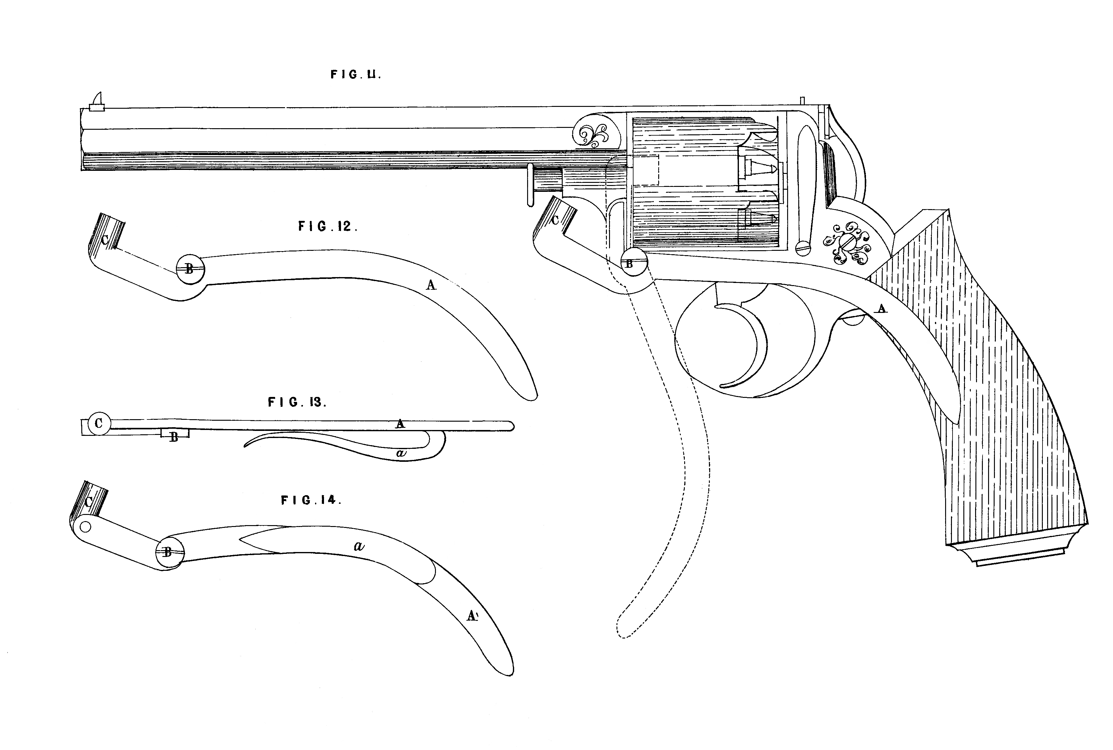
Figs. 11, 12, 13, and 14 relate to the last part of my Invention. Fig. 11 represents a revolving chamber fire-arm with the improved loading lever applied thereto. A is the lever, turning on a fulcrum at B under the front face of the revolving cylinder. The lever A extends backwards from the fulcrum B, a recess being formed in the stock of the fire-arm to receive it; or, if preferred, it may be fitted so as to be along the outside of the stock; C is the loading end of the lever, which is so constituted as, when the reverse end of the lever is drawn downwards, it may be made to pass into the loading chamber as the latter is brought into position. The lever may be varied in form, and may be retained in its position of rest by a stud on the side of the stock falling into a cavity in the lever, or by other convenient means. Fig. 12 is a separate view of the loading lever. Figs. 13 and 14 are side and edge views of the loading lever, having a spring a attached, which is intended to serve as a belt spring. Fig. 14 shews a jointed end for striking the ball.
Having thus described the nature of my Invention, and in what manner the same is to be performed, I would have it understood that I do not mean or intend to confine myself to the precise forms and arrangements of the parts represented and described; but what I claim as of my Invention is,—
First, the safety catch for retaining the cock, with the means of liberating the latter in such a manner as to act perfectly independently of the lock or trigger.
Secondly, the mode of uniting two or more rifle barrels so that they may be separated and rejoined at will.
Thirdly, the mode described of rifling gun barrels.
Fourthly, the method of making compound rifle patches as described.
And, lastly, the loading lever so fixed as to be capable of passing into the loading chamber and ramming the charge without any special adjustment of the chamber, as described.
In witness whereof, I, the said John Rigby, have hereunto set my hand and seal, this Ninth day of March, in the year of our Lord One thousand eight hundred and fifty-five.
JOHN RIGBY. (l.s.)
Signed, sealed, and delivered in the presence of
John NEmETON,
5, Malpas Street,
Dublin.