
British 2473
LETTERS PATENT to Charles Crickmay, of the Lozells, Handsworth, in the County of Stafford, Gun Manufacturer, for the Invention of “ IMPROVEMENTS IE SlEGLE AED REPEATING OR ReVOLVIEG FlRE-ARMS, AED IE THE
Mode of Attachieg Bayoeets to Breech-loading Fire-arms.”
Sealed the 18th May 1855, and dated the 23rd November 1854.
PROVISIONAL SPECIFICATION left by the said Charles Crickmay at the Office of the Commissioners of Patents, with his Petition, on the 23rd November 1854.
I, CnARLES Crickmay, of the Lozells, Handsworth, in the County of Stafford, Gun Manufacturer, do hereby declare the nature of my “ Improvements in Single and Repeating os Revolving Fire-arms, and in the Mode op Attaching Bayonets to Breech-loading Fire-arms,” to be as follows:—
Firstly, in connecting the barrel and stock, or lock part of breech-loading fire-arms, without any regard to the number of chambers the breech thereof may contain, by a stout immoveable pin or bar, on which the breech revolves; and at the base or back of and around such pin, where it unites itself with the lock and stock, are two or more inclined planes, their line of inclination rising towards the muzzle of the gun; and in connection with their inclined planes are counter inclined planes, attached to a spring lever, which, working on the pin bar or breech, being placed between the barrel and the spring lever, it is evident that as such lever is made to revolve against the inclined planes, that the breech is forced into complete contact with the barrel; the end of which being a frustum of a cone, and that part of the breech chamber in contact with it being countersunk, the union is of the most perfect kind.
Secondly, in forming the pin or bar on which the breech revolves in such a way that I may dispense with the base or projecting part for the inclined planes, and in that case I allow such pin or bar to extend long enough to be united to the part that carries the lock and stock by screwing or otherwise, the inclined planes being formed on that part, and the counter inclined planes attached to the lever, so as to be applied as before describ’d.
Thirdly, my Invention consists in applying to such fire-arms as are hereinbefore described a self-priming apparatus, which consists of a hollow’ chamber for containing percussion caps, placed in such a manner that as the nipple comes before an apperture in such chamber, a cap is placed thereon by means of a spring.
Fourthly, in attaching bayonets by a hinge joint near the muzzle of breechloading fire-arms, so that the blade thereof shall lie on the under side of the barrel when out of use, but which will instantly fix itself for use by relieving a spring or detent.
SPECIFICATION in pursuance of the conditions of the Letters Patent, filed by the said Charles Criekmay in the Great Seal Patent Office on the 23rd May 1855.
TO ALL TO WHOM THESE PRESENTS SHALL COME, I, Charles Crickmay, of the Lozells, Hands worth, in the County of Stafford, Gun Manufacturer, send greeting.
WHEREAS Her most Excellent Majesty Queen Victoria, by Her Letters Patent, bearing date the Twenty-third day of November, in the year of our Lord One thousand eight hundred and fifty-four, in the eighteenth year of Her reign, did, for Herself, Her heirs and successors, give and grant unto me, the said Charles Crickmay, Her special license that I, the said Charles Crick-may, my executors, administrators, and assigns, or such others as I, the said Charles Crickmay, my executors, administrators, and assigns, should at any time agree with, and no others, from time to time and at all times thereafter during the term therein expressed, should and lawfully might make, use, exercise, and vend, within the United Kingdom of Great Britain and Ireland, the Channel Islands, and Isle of Man, an Invention for “Improvements in Single and Repeating oe Revolving Fiee-aems, and in the Mode of Attaching Bayonets to Breech-loading Fire-arms,” upon the condition (amongst others) that I, the said Charles Crickmay, by an instrument in writing under my hand and seal, should particularly describe and ascertain the nature of the said Invention, and in what manner the same was to be performed, and cause the same to be filed in the Great Seal Patent Office within six calendar months next and immediately after the date of the said Letters Patent.
NOW KNOW YE, that I, the said Charles Crickmay, do hereby declare the nature of my said Invention, and in what manner the same is to be performed, to be particularly described and ascertained in and by the following statement (that is to say)
My improvements relate to the description of fire-arms known as breechloading, and consist as follow:—
Firstly, in connecting the barrel and stock, or lock part of breech-loading fire-arms, (without any regard to the number of chambers the breech thereof may contain,) by a stout immoveable pin or bar, on which the breech revolves, and at the base or back of and around such pin, where it unites itself with the lock or stock, are two or more inclined planes, their lines of inclination rising towards the muzzle of the gun ; and in connection with these inclined planes are counter inclined planes, attached to a spring lever, which, working on the pin bar or breech, and the breech or counter-breech being placed between the barrel and the spring lever, it is evident that as such lever is made to revolve against the inclined planes, that the breech or counter-breech is forced into complete contact with the barrel, the end of which being a frustrum of a cone, and that part of the chamber or counter-breech in contact with it being countersunk, the union is of the most perfect kind.
Secondly, in forming the pin or bar on which the breech revolves in such a way that I may dispense with the base or projecting part for the inclined planes; and in that case I allow such pin or bar to extend long enough to be united to the part that carries the lock and stock by screwing or otherwise, the inclined planes being formed on that part, and the counter inclined planes attached to the lever, so as to be applied as before described.
Thirdly, my improvements consist in applying to such fire-arms as are herein-before described a self-priming apparatus, which consists of a hollow chamber for containing percussion caps, placed in such a manner that as the nipple comes before an aperture in such chamber, a cap is placed thereon by a spring, or other suitable means.
And, lastly, in attaching bayonets by a hinge joint near the muzzle of breechloading fire-arms, so that the blade thereof shall lie on the under side of the barrel when out of use, but which will instantly fix itself for use by relieving a spring or detent.
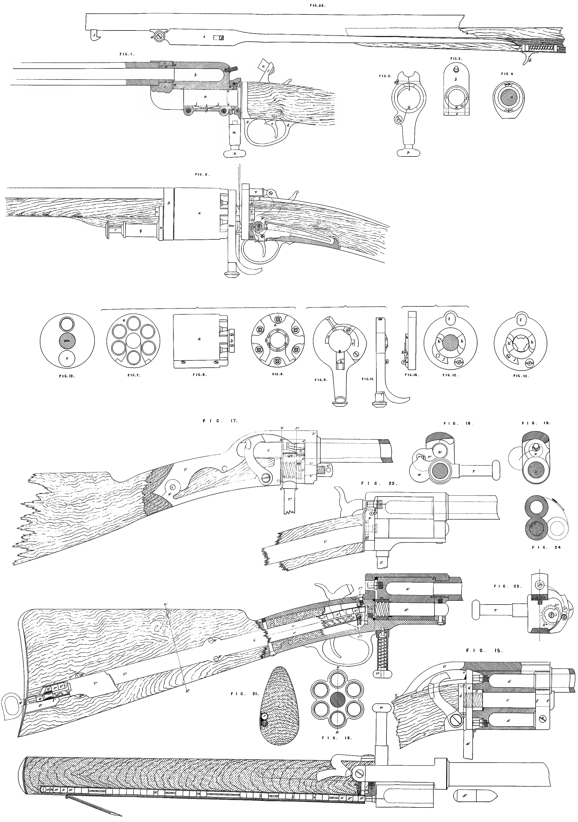
And in order that my Invention may be most fully understood and readily carried into effect, I will proceed to describe the Drawings hereunto annexed, in the various Figures of which the same letters are used to indicate the same parts.
Description of Drawings.
Fig. 1, Sheet 1, represents as much of a single shot breech-loading gun as may be necessary for exhibiting my improvements, which consist in forging the pin a in such a manner that it may not only form an axis for the breech b to revolve on, but also forms a connection between the stock and the barrel, which is united to it by a screw, as exhibited in section at c, c, c, c, while the other end of the pin is enlarged, for the purpose of forming two or more inclined planes, which project forwards towards the breech. This end of the pin, forming these inclined planes, is expanded, so as to form the “ break-off” of the gun at the stock, and is furthermore lengthened out at bottom to form a strap, by which it may be firmly attached to the wood stock, and to carry the various parts of the lock, as indicated by the guard d, trigger e, and hammer/, the latter of which works on the right-hand side of the stock. I have shewn the breech b in section, so as to better exhibit its mode of working; and which I have also shewn in an end view at Figure 3, where it will be seen that the part g may be taken out by removing the screws h, h; this is necessary in order to put on or take off the breech from the pin a. j, j, is a spring, secured to the removeable part (g) of the breech by the screw or pin k, the use of which spring is to generate sufficient friction to prevent the breech working loosely on the pin. I, Z, is a projecting collar, on which the lever m works, having in its under side two holes, better seen in dotted lines at n, n\ Figure 3. These holes arc intended to receive the small pin o, which is pressed forward by a helical spring in the lever m, and may be removed by pulling down the knob p. This lever is shewn more fully at Figure 2 ; and it will be seen, that having to be put on over the collar Z, it becomes necessary to open it, which is effected by the hinge joint at r, and is secured in its closed position by tho screw q; the projecting part s works in the groove in the collar r, so as to hold the lever more firmly on it; Figure 4 representing a section of the pin as taken through u, w, and is here drawn to shew the form of the break-off; as also the inclined planes t, t, which correspond with and work against the inclined planes v, v% in the lever, their inclination being shewn by arrows, and supposed to rise towards the barb.
Having thus described the parts, I will now describe their several uses. By pulling down the knob p, the pin o is removed from the hole n in the projecting collar l, and by pulling the lever around, until the pin o is pressed (by the spring in the lever) into the hole the inclined planes are separated, and the lever and breech being pulled toward the stock, the conical end of the barrel is relieved from the countersunk portion w of the breech; and the pin o, being still in the hole nl, the breech is carried with it, and the chamber exposed on the right-hand side of the gun or pistol, into which the cartridge may now be placed. The lever, and with it the breech, is now brought back, the breech chamber coinciding with the bore of the barrel, and the lever still in the hole n1; then, by pulling the pin o, by means of the knob p, out of the hole and bringing the lever into the position shewn, the inclined planes work on each other, and force the breech forward into complete and thorough contact with the barrel, and the pin dropping into the first hole n, the whole is held firmly together, and ready to receive the percussion cap on the nipple, to be exploded by the hammer x, which is hollowed out in the ordinary manner.
Fig. 5 represents my improvements in polychambered fire-arms, and exhibited in a six-shot gun, and is only the carrying out of the before-described method to a greater extent, the parts being shewn separate, as before, a is a breech containing the chambers, one of which is shewn detached in front and end views at Figures 6, 7, and 8, can be taken out, so that the breech may go on the pin, as in the gun before described; there is also a similar collar at b, but in this gun it contains as many holes as chambers, namely six, shewn at c, c, &c. The lever, Figure 9, is also similar to that in Figure 1, but is used in rather a different way, as will presently be described. Figure 10 is a view of the front plate d, of Figure 5, into which the barrel is screwed, and through the hole e the chambers are loaded. Fig. 11 is a side view of the lever, shewing the projection and inclination of the inclined planes /, f1, the pin g, as exhibited at Figure 9, having the same use as that used for the single gun, marked o, Figure 2. Fig. 12 is a view of the break-off and the inclined planes h, h1; j being a kind of detent, that keeps the pin g out of the next hole, till it gets to the third from the bottom, and this is done by having a projection, as at ifc, Figure 11, on the pin g, which, when the pin is pulled down and moved a little to the side, rests on the detent until the pin arrives at the third hole; the especial use of this I will herein-after describe.
Fig. 13 shews a mode of constructing the break-off by ‘which a solid breech may be used. The pin on which the lever revolves being made detachable, the breech and lever may be slid on; and the end of the pin at s, Figure 5, being made to correspond to the hole in the centre of the break-off, and also having inclines on it, it is put through such hole and turned one-fourth of a revolution, and ultimately secured by the screw n, passing through the front strap l, Figure 5, through the pin, and screwed into the enlargement of the under strap at m. Fig. 14 is a side view of the break-off, the part at o being pressed forward by a helical spring behind (not shewn), for the purpose of forcing forward the lever and breech when the conical end of the barrel is opposite the countersunk portion of one of the chambers.
Having thus shewn the peculiar difference between the details of this and the first described gun, I will now describe the method of using it.
The manner of loading may be seen by referring to Figure 5. p is a slide, hung on the front of the barrel plate d, having a box q, containing a helical spring and the rod r, which is mounted at its outer extremity by a flat head, and at the other is enlarged into a piston fitting loosely the breech chambers. To load, the slide is moved to the side, and the cartridge pushed in through the hole c, Fig. 10; the slide being then brought in front, and the rod head being struck with the hand, the piston or plunger descends into the chamber, and forces the charge into its place; the like is repeated by moving round the breech ; but to effect this the parts must be in a peculiar relation to each other, now to be described, that is to say, the pin g in the lever must be withdrawn from its hole in the collar b, and the lever moved until the pin g rests on the detent j; by then pressing the breech in the direction of the stock (so as to disengage the barrel and chamber), it may be rotated alone. Supposing now the whole of the chambers to have been charged, the first may be fired by merely cocking the gun and firing in the ordinary way; this being done, it becomes necessary to bring another chamber opposite the barrel: put the hammer to half-cock, disengage the pin g from the lower hole, move the lever by itself until the pin drops into another hole, which will be the third, it having been prevented from going into the second by the projection k (of the pin g, Figures 0 and 11), having been detained by the detent j% keeping the left hand at this time on the breech and pressing downward, the barrel and ; chamber will be disengaged; now move the lever, and with it the breech back again, and by this time the next chamber comes opposite the barrel; the pin will be disengaged from the third hole, and the breech will be pushed forward by the helical spring behind the part o\ and so prevented from rotating farther; the inclined planes now come into action, and by the time the pin and j lever are opposite the bottom hole, the inclined planes will have forced the breech and barrel into perfectly gas-tight contact; the pin, then being forced into the bottom hole, holds all the parts in safe connection; the gun may be fired, and the operation repeated in far less time than it takes to read the description of it. I find it more convenient to attach to the hammer a horizontal striker v, working through the hole t, in Figures 12 and 13, as it is susceptible of a more direct stroke on the nipple. The only peculiarity in the locks consist in putting a screw w through the tumbler x and into the axis y of the hammer, thereby holding it quite secure, and allowing the details to be taken more easily apart. It will be seen, by referring to Figure 5, that the peculiar construction of the striker v is well adapted for the application of a needle, and so making it into a needle gun.
Fig. 15, Sheet 2, also represents as much of a six-shot revolving gun, carbine, or pistol necessary for exhibiting my improvements, and which I have drawn with a view of shewing that the inclined planes, named in the first head of this my Specification, may be continued around in the form of a screw, which may contain one or more threads, such screw being cut on the centre pin or bar on which the breech or chambers revolve, and shewn in this Figure in dotted lines. A1, A1, represents the two exposed chambers that would be exhibited in a vertical section of this part, which is shewn in an end view at Figure 16, the section being taken through Bl, B1; C\ being the centre pin, forged in connection with the base or back plate D1, and straps shewn in dotted lines E1, E1, to which the stock is attached; the part P, partly shewn in section, forms the top strap, and is secured to the pin Cl by fitting down between the shoulders gl9 gl, of the pin C\ the vacant part being afterwards filled up and secured by the screw H1, the other end of the strap being securely attached to the strap E1 and stock by the screw I1, the barrel being attached to this strap by tapping, as in Figure 1, Sheet 1, the end of which being bevelled, for the purpose of fitting into the corresponding bevel or countersunk chambers of the breech, to ensure a more perfect union, and which is effected in this instance, as in Figure 1, plate K\ collar L1, spring lever M1, and catch N1, shewn partly broken off, at the back of which, at J1, J1, is a projecting rim surrounding the screw, and is here introduced to prevent any corrosion or dirt getting to it, there being a corresponding sunken circular groove in the base or back plate Dl for receiving it when the plate Kl is brought back by the lever M1 for the purpose of freeing the breech from the conical projection on the barrel, so as to allow the breech to revolve; and I will further observe that I have thought it necessary to allow the back plate K1 to extend up and abut back against an inclined groove cut on the under side of the strap Fl, as shewn at O1.
Fig. 17, Sheet 2, represents another application of a lever working on inclined planes, or a screw, as a means of cutting off the escape of gas in breechloading guns, and on the plan as here exhibited I am enabled to shorten the pin on which the screw is cut; I mainly effect this by loading from behind, as I am enabled to open the chamber right at its base by causing the part Pl, to which the nipple is attached, to revolve on the centre pin, for the purpose of receiving the charge, as will bo best understood by referring to Figure 18, which is a section of Figure 17, taken through Q1, Ql. It1 represents the bore or interior of the barrel, the double circular lines representing its conical or bevel edge; the part P1 with the nipple being removed or turned down to allow the charge to be placed in, and which is readily effected by first laying the cartridge in the hollow cavity S\ and the part P1 being turned down by the action of the lever T1 and screw U1 and groove V1, indicated by dotted lines; the chamber being thus opened, the cartridge is pushed forward into the chamber, when the plate Pl is brought back into its first position and forced into perfect contact by the back plate Wl advancing forward on the screw by the lever Tl, and further pressed against the part Pl, by abutting back against the inclined groove placed on the under side at X1 of the strap Yl, Y1, which strap I have drawn in full, to show that it is first attached to the bar E11, on which Pl revolves by a conical pin, shewn in dotted lines at Z1, Z1, and there secured by the nut A11, which nut has a hole through it, by which it may be screwed up or removed when required; and the other end of the strap Y1 is fitted into a circular boss Bu, which boss forms part of the under strap, the wood of the stock being cut away in this Figure for the purpose of shewing the form of the straps, and how they are attached and united to the stock, which is done by screws passing through the holes C11, Cu. Before concluding the description of this Figure, I may simply observe that I have introduced a projecting rim on the back of the plate W1, for the purpose of keeping out dirt or moisture, as described at Jl, Jl, Figure 15 ; (and I will further observe, that I have shewn in dotted lines at dl\ dn, the end of the barrel conical, as in the other Figures, as it tends to improve the juncture by its expansion when in use, thereby making it gas-tight; Figure 19 being a section of Figure 17, taken through /ll,/11, and is introduced to shew the position of the part P1 when placed before the chamber, as also shewing by the dotted lines that it works on the bar E11, E11.) The great strength and simplicity of this fire-arm is peculiarly adapted for the use of cavalry, the more so when fitted with the self-priming aparatus, named under the third head of this my Specification, which I will proceed to describe.
Fig. 20 represents a breech-loading gun, partly shewn in section, with the barrel broken off, in the stock of which I have exhibited a cavity for holding caps, as also the manner in which they will be placed on the nipple when required. The barrel is united to the strap, as before described in the other Figure, and the breech Gu revolving on the pin II11, and actuated by the lever and spring working on the screw, as before described. I11,111, is a tube, extending the length of the stock, partly shewn in section, and calculated to hold about seventy percussion caps; this tube is drawn somewhat in the form of a figure 8, as shewn at J11, Figure 21, which is a section taken through fc11, F1, of the last Figure. The double tube I11,111, is soldered (or otherwise united) to the front plate L11, L11, which is partly removed, to exhibit the priming tube and screw, the whole being sunk into the stock flush, and secured by screws, as at Mn, M11, Mu, M11; and at the butt end the front plate L11 is joined with a hinge joint, which is represented open, for the purpose of shewing that the caps are dropped into the tube at this part until the hole or tube is filled up. Nu, N11, N11, Nu, N11, N11, represents the caps, and On the follower, which works from end to end of the tube, carrying the caps before it in regular succession by means of the screw P11, P11, which works on centres fixed at each end, as represented at Q11, Q,11, the axis of the screw being shewn at each end in dotted lines. When the chamber for the percussion caps requires filling, a small key, shewn in dotted lines at Ru, is inserted through the butt plate, and passes over a square formed on the extreme end of the screw, and by this means the screw may be readily turned around until the follower Q11 is brought back into the position shewn, when the key is removed and placed in the hollow cavity of the butt at Sn, provided for it, the caps being deposited in the tube, as shewn; the cover T11 may now be closed down and retained by any suitable spring or catch. 1 will now proceed to describe how the caps are placed upon the nipple when required. The pin U11 is pulled down by the knob V11, and the lever pressed towards the left-hand side of the gun, and in doing so it works back on the screw, thereby relieving the breech from the barrel at W11, bringing the breech or chamber down on a level with the pin IIU, on which it works, and in doing so it removes a circular plate from before the priming tube, so that the nipple may come opposite to it, and at the same time, by means of a spring paul working on the inside of the circular plate, the toothed wheel X11, X11, is made to revolve one-third of a revolution, in doing which the globular pinion Y11 will make one revolution, and this pinion being secured to the end of the screw Pu, the follower On will approach towards the nipple the exact length of. one cap, which in its forward course will be forced on the nipple, which will at that time stand before the aperture, as exhibited in dotted lines at Zu; the replacing of the breech now primed and loaded will have the effect of drawing back the circular plate and covering up the aperture.
Fig. 22 represents a top view of the barrel and strap, and exhibiting a sectional lengtlnvay view of the stock, taken through the tube that carries the caps, shewing the position of the lever and breech or chamber ready to receive the percussion cap Nu and cartridge, which is represented at A111 of this Figure; the back part of the strap, to which the pin II is attached, being shewn in section, for the purpose of shewing the toothed wheel X11 and ratchet wheel Jnl, working freely on a screw pin mul, mni. Fig. 23 is the same as Figure 20, with the butt and lever broken ofF for the convenience of space, and is drawn for the purpose of shewing the circular plate B111, which is united to the breech by the strap C111, that as the breech is brought down for the purpose of loading and priming, as shewn by the dotted circles and arrow, Figure 24, this circular plate will descend with it and open the aperture to allow a cap to come through when the nipple is presented, the nipple being shewn in dotted lines in that position ready for receiving the cap, as also the slot cP11, dm, through which the paid works, and which is exhibited at Figure 221, which is a section of Figure 20 taken through flu,fm, the breech G11 being brought down in the position for loading and priming. The manner in which the latter is effected is here best exhibited. The paid II, which is united to the inside of the circular plate BUI, B’n, Figure 23, by a hinge or other joint, and forced towards the ratchet wheel J111 by a spring, so that, in descending to the position shewn, the ratchet wheel Jul has been turned around one-third of its circumference, at the same time turning the toothed wheel, shewn in dotted lines, in the same proportion, thereby turning the circular pinion Y111, which is fixed on a square filed on the end of the screw, as shewn at P11, P11, Figure 20, as a means of carrying forward the caps through the hole KU1 to the nipple, as before described ; the breech may now be turned up, with the cap on the nipple into the position shewn by the dotted lines at L111, as shewn at Figure 22l, ready for discharging. When I apply a self-priming aparatus to pistols, I prefer using an endless chain or band for carrying forward the caps, as it could be worked over a curved grove, which would be more in accordance with the form of the stock of such description of fire-arms, the endless chain or flexible bend being actuated by similar means, as herein described.
And the last part of my improvement in fire-arms relate to the mode of attaching bayonets to breech-loading guns, such as carbines or muskets, and consist in applying underneath the barrel a hinge joint, as at a, Figure 25, Sheet 1, upon which the bayonet works. At the point of the bayonet is seen the detent b, actuated by the helical spring c, and is relieved by pulling the trigger if, and there being a strong spring at the part e, when such triger is drawn back, the bayonet flies up, and is held in the forward position by the catch /taking hold of the small bar <7 in the centre of it, being pressed forward to its work by a helical spring behind it; the ends of the bar^ comes through and projects on the outside of the bayonet, so as to be taken and pressed back by the fingers, which of course relieves the bayonet, and allows it to be put back into the position shewn in the Drawing. Having thus described the nature of my improvements in breech-loading fire-arms, and various ways in which the same may be carried into effect, I will observe that in the Drawings hereunto annexed I have studied to represent my various improvements as best suited for offensive and defensive warfare, but which may be varied in all their general detail for ordinary purposes; and I would have it understood that I do not restrict myself to any particular form, dimensions, or material, so long as the principle of my various improvement is adhered to, whether applied to guns or pistols; and I further declare that what I claim as my Invention is,— Firstly, the mode of constructing breech-loading single shot fire-arms, as exhibited at Figures 1,17, and 20, as far as their construction relate to the bar on which the breech revolves, and to the circular inclined planes and counter inclined planes with which the breech and barrel are forced into contact, as also in the form of the juncture of the barrel, with the breech or counter-breech of such fire-arms. Secondly, I claim the mode of constructing the locks for such breech-loading guns as herein described and exhibited at tt/, a?, y, Figure 5, without any regard to the number of chambers such guns may contain to which such locks may be applied. Thirdly, I claim a mode of constructing revolving or repeating fire-arms, as exhibited at Figures 5 and 15, which are drawn to illustrate the various applications of the inclined planes as applied to such guns; I also claim the mode of uniting the pin on which the chambers revolve, as described at n and s, Figure 5, and in a separate view at Figure 13. Fourthly, I claim the application to such fire-arms as herein described of a self-priming apparatus, without confining myself to the exact detail drawn and exhibited at Figures 20, 21, 22, and 221, Sheet 2, as I may in some instances find it more convenient to substitute a flat chain or band for carrying forward the percussion caps, or they may be impelled forward by an helical spring placed in the tube. And, lastly, I claim the application to breech-loading guns, whether single or repeating, of a fixed bayonet, as exhibited at Sheet one, Figure 25, without confining myself to tlie exact details as to the mode of connecting and retaining1 it in its positions. In witness whereof, I, the said Charles Crickraay, have hereunto set my hand and seal, this Twenty-first day of May, in the year of our Lord One thousand eight hundred and fifty-five. CHARLES CRICKMAY. (l.s.)