
British 2602
LETTERS PATENT to William James Harvey, of Exeter, Gunmaker, for the Invention of “ Improvements nr Fixe-aems when Revolving Barrels axe used/’
Sealed the 20th March 1855, and dated the 11th December 1854.
PROVISIONAL SPECIFICATION left by the said William James Harvey at the Office of the Commissioners of Patents, with his Petition, on the 11th December 1854.
I, William James Harvey, of Exeter, Gunmaker, do hereby declare the nature of the Invention for “ Improvemehts nr Fire-arms whem Revolving Barrels are used ” to be as follows:—
This Invention is applicable to those classes of fire-arms now known as “revolvers,” and the improvements consist, first, of a mode of constructing a fire-arm of this description with reference to facilitating the loading of the several short barrels; and, secondly, the Invention consists of applying to the lock of such a description of fire-arm a second safety bolt. For these purposes, there is a slot formed in the enlargement made under the long barrel to receive the end of a lever, and the ramrod is attached to this lever by a pin joint. The stock is made with a recess to receive the lever and ramrod, such recess being closed in by a door or cover. Heretofore there have been safety bolts used for preventing the cock or hammer being moved by accident, which to some extent has succeeded, but I add a second bolt to lock or fasten the safety bolt, by which absolute safety is obtained.
SPECIFICATION in pursuance of the conditions of the Letters Patent, filed by the said William James Ilarvey in the Great Seal Patent Office on the 11th June 1855.
TO ALL TO WHOM THESE PRESENTS SHALL COME, I, William
James Harvey, of Exeter, Gunmakcr, send greeting.
WHEREAS Her most Excellent Majesty Queen Victoria, by Her Letters Patent, bearing date the Eleventh day of December, in the year of our Lord One thousand eight hundred and fifty-four, in the eighteenth year of Her reign, did, for Herself, Her heirs and successors, give and grant unto me, the said William James Harvey, Her special licence that I, the said William James Harvey, my executors, administrators, and assigns, or such others as I, the said William James Ilarvey, my executors, administrators, and assigns, should at any time agree with, and no others, from time to time and at all times thereafter during the term therein expressed, should and lawfully might make, use, exercise, and vend, within the United Kingdom of Great Britain and Ireland, the Channel Islands, and Isle of Man, an Invention for “ Improvements in Fire-arms when Revolving Barrels are used,” upon the condition (amongst others) that I, the said William James Harvey, by an instrument in writing under my hand and seal, should particularly describe and ascertain the nature of the said Invention, and in what manner the same was to be performed, and cause the same to be filed in the Great Seal Patent Office within six calendar months next and immediately after the date of the said Letters Patent.
NOW KNOW YE, that I, the said William James Harvey, do hereby declare the nature of the said Invention, and in what manner the same is to be performed, to be particularly described and ascertained in and by the following statement thereof (that is to say):—
This Invention is applicable to those classes of fire-arms now known as “ revolvers,” and the improvements consist, first, of a mode of constructing a fire-arm of this description with reference to facilitating the loading of the several short barrels; and, secondly, the Invention consists of applying to the lock of such a description of fire-arm a second safety bolt For these purposes, there is a slot formed in the enlargement made under the long barrel to receive the end of a lever, and the ramrod is attached to this lever by a pin joint. The stock is made with a recess to receive the lever and ramrod, such recess being closed in by a door or cover. Heretofore there have been safety bolts used for preventing the cock or hammer being moved by accident, which to some extent have succeeded, but I add a second bolt to lock or fasten the safety bolt, by which absolute safety is obtained.
And in order that my said Invention may be most fully understood and readily carried into effect, I will proceed to describe the Drawing hereunto annexed.
Description of the Drawing.
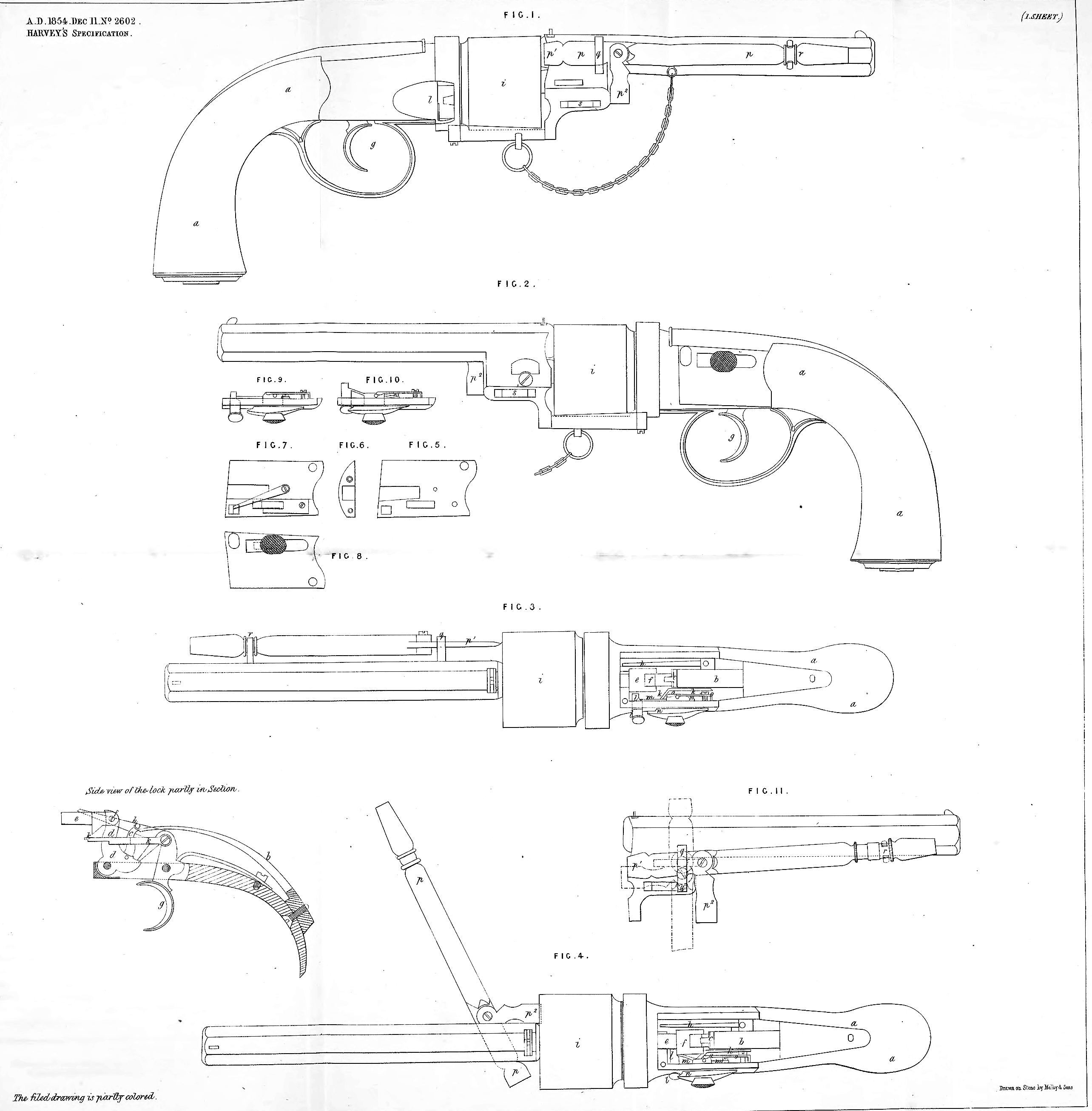
Figure 1 is a right-hand side view, of a pistol constructed according to my Invention; Figure 2 is a left-hand side view of the same; Figures 3 and 4 are plans, a is the stock of the pistol, in the interior of which are the parts forming the lock ; b is the main spring, which is connected by the link c to the bell-crank lever d9 to which the hammer e is hinged at f;g is the trigger, connected with which there is a spring click or driver, which, when the trigger is pulled, comes in contact with the tail of the lever d9 and thus draws back the hammer. Connected with this click is the arm h9 which, when the trigger is pulled, comes in contact with the ratchet teeth on the revolving chamber i, and thus causes them to rotate on the same axis. With this click is also the pin k, which, by coming in contact with projections on the chambers, stops them at the required positions. All the parts which I have at present described are of an ordinary construction. I is a safety stop or bolt, to prevent the hammer e from coming in contact with the nippers while loading; this safety stop or bolt is pressed upon by a spring m, so that it springs out again when the pressure of the hammer is withdrawn by pulling the trigger, n is a second bolt, for permanently fixing the safety stop or bolt l9 so as to prevent the discharge of the pistol on pulling the trigger, any accident while loading or carrying when loaded, o is a spring for holding the second bolt in position. The arrangement of these bolts is clearly shown at Figures 5, 6, 7, 8, 9, and 10. Figures 5 and 6 show an inside and an end view of the side plate of the lock without the working parts ; Figure 7 shows an interior, and Figure 8 an exterior, view of the same with the working parts; and Figures 9 and 10 are plan views of the same parts, showing the bolt in and out of position, p is a detached lever ramrod; it is held when out of use by the eye q and the spring catch r, as seen in Figures 1 and 3. When in use, the end p1 is placed in the slot s, and the piece p2 enters the chamber to be rammed; or the eye q may turn on a centre (as seen in Figure 11) to allow the piece p2 to enter the chamber to be rammed. At the end p5 of the ramrod there is a nipple key, and at the end pl a tumscrew. The groove t in the body of the lock is for the purpose of allowing the exploded caps to fall out.
In witness whereof, I, the said William James Harvey, have hereunto set my hand and seal, this Seventh day of June, in the year of our Lord One thousand eight hundred and fifty-five.
WILLIAM JAMES HARVEY. (l.s.)
Witness,
Samuel Harvey, A. B., Clerk,
19, Dix’s Field.