
British 1098
LETTERS PATENT to William Henry Dearing Granville, of 44, Holborn Hill, in the City of London, Gun Manufacturer, for the Invention of “ Improvements in Fire-arms and in the Means of Loading the same.”
Sealed the 16th October 1857, and dated the 18th April 1857.
PROVISIONAL SPECIFICATION left by the said William Henry Dearing Granville at the Office of the Commissioners of Patents, with his Petition, on the 18th April 1857.
I, William Henry Dearing Granville, of 44, Holborn Hill, in the City of London, Gun Manufacturer, do hereby declare the nature of the said Invention for “ Improvements, in Fire-arms and in the Means op Loading the same,” to be as follows:—
In a magazine or cartridge chambers consisting of any number of tubes, each tube containing a spiral spring and forcer to push forward the cartridges as required, and each forcer having a rod with a lock spring to confine the spiral spring while the magazine is being loaded, which magazine is rotated upon centres bring up each tube as required, also fitted with spring or springs to retain it in the required position. Next, in a horizontal revolving cylinder moving in the framework of the fire-arm, bored with any number of chambers opposite to each other, so that while one chamber is brought into a line with the barrel of the fire-arm, the opposite chambers receive a cartridge from the magazine and brings it round to the barrel to be discharged. This is effected by certain actions of the lock acted upon by the trigger, which, on being* pressed by the finger, sets in motion a driver, which rotates the horizontal cylinder, and at the same time propels a bar, which raises the hammer to the point required, when it releases it to discharge the fire-arm. On removing the pressure from the trigger, a spring acting upon it brings it back to its former position, and with it also the driver and bar, each of which is provided with a spring to keep it in its proper position. These several parts (and their actions) are placed under the cylinder in the framework of the fire-arm, thereby leaving the top of the pistol or fire-arm entirely clear, so that nothing impedes the aim. To ensure the accuracy of such aim a sight marked for certain distances is fixed thereon. The cartridges used in this method are made to contain an explosive substance, or percussion cap, or powder; a needle being struck by the hammer explodes the charge. The cartridge cases are made of metal of any kind, so that they can be refilled and used again if required, or they may be made of a chemical, prepared paper satuated with nitric acid, or other acid possessing similar properties), cloth or skin, which explodes or consumes on the discharge of the fire-arm.
I propose applying the improvements herein-before mentioned, with slight modifications, to fire-arms with two or more barrels.
SPECIFICATION in pursuance of the conditions of the Letters Patent, filed by the said William Henry Dearing Granville in the Great Seal Patent Office on the 16th October 1857.
TO ALL TO WHOM THESE PRESENTS SHALL COME, I, William Henry Dbarinq Granville, of 44, Holbom Hill, in the City of London, Gun Manufacturer, send greeting.
WHEREAS Her most Excellent Majesty Queen Victoria, by Her Letters Patent, bearing date the Eighteenth day of April, in the year of our Lord One thousand eight hundred and fifty-seven, in the twentieth year of Her reign, did, for Herself, Her heirs and successors, give and grant unto me, the said William Henry Dearing Granville, Her special license that I, the said William Henry Dearing Granville, my executors, administrators, and assigns, or such others as I, the said William Henry.Dearing Granville, my executors, administrators, and assigns, should at any time agree with, and no others, from time to time and at all times thereafter during the term therein expressed, should and lawfully might make, use, exercise, and vend, within the United Kingdom of Great Britain and Ireland, the Channel Islands, and Isle of Man, an Invention for “ Impbovements in Fibe-abms, and in the Means op Loading the same/1 upon the condition (amongst others) that I, the said William Henry Dearing Granville, my executors or administrators, by an instrument in writing under my, or their, or one of their hands and seals, should particularly describe and ascertain the nature of the said Invention, and in what manner the same is to be performed, and cause the same to be filed in the Great Seal Patent Office within six calendar months next and immediately after the date of the said Letters Patent.
HOW KNOW YE, that I, the said William Henry Dearing Granville, do hereby declare the nature of my said Invention, and in what manner the same is to be performed, to be particularly described and ascertained in and by the following statement (that is to say):—
The object of this Invention is to produce a fire-arm capable of being effectually and safely discharged and recharged many times without the loss of time consequent upon loading after every fire in the ordinary manner. I am aware that several persons have patented fire-arms having this object in view, but 1 do not think they have succeeded in producing one capable of ensuring a great number of discharges deliverable with certainty and at the same time with safety, in which latter particular my improvements will be found of eminent importance. I have shewn in this my Specification the improvements as applied to a pistol, with modifications, which may be made without any departure from the principle of my improvements. Fire-arms of larger calibre may be constructed with magazines or cartridge chambers, and otherwise fitted for the purpose of securing many successive discharges without reloading. It is needless to describe the manner of making the barrel, stock, or the various parts herein mentioned or referred to, as all persons conversant with or skilled in the manufacture of fire-arms are able to understand or make the same without any instructions from me.
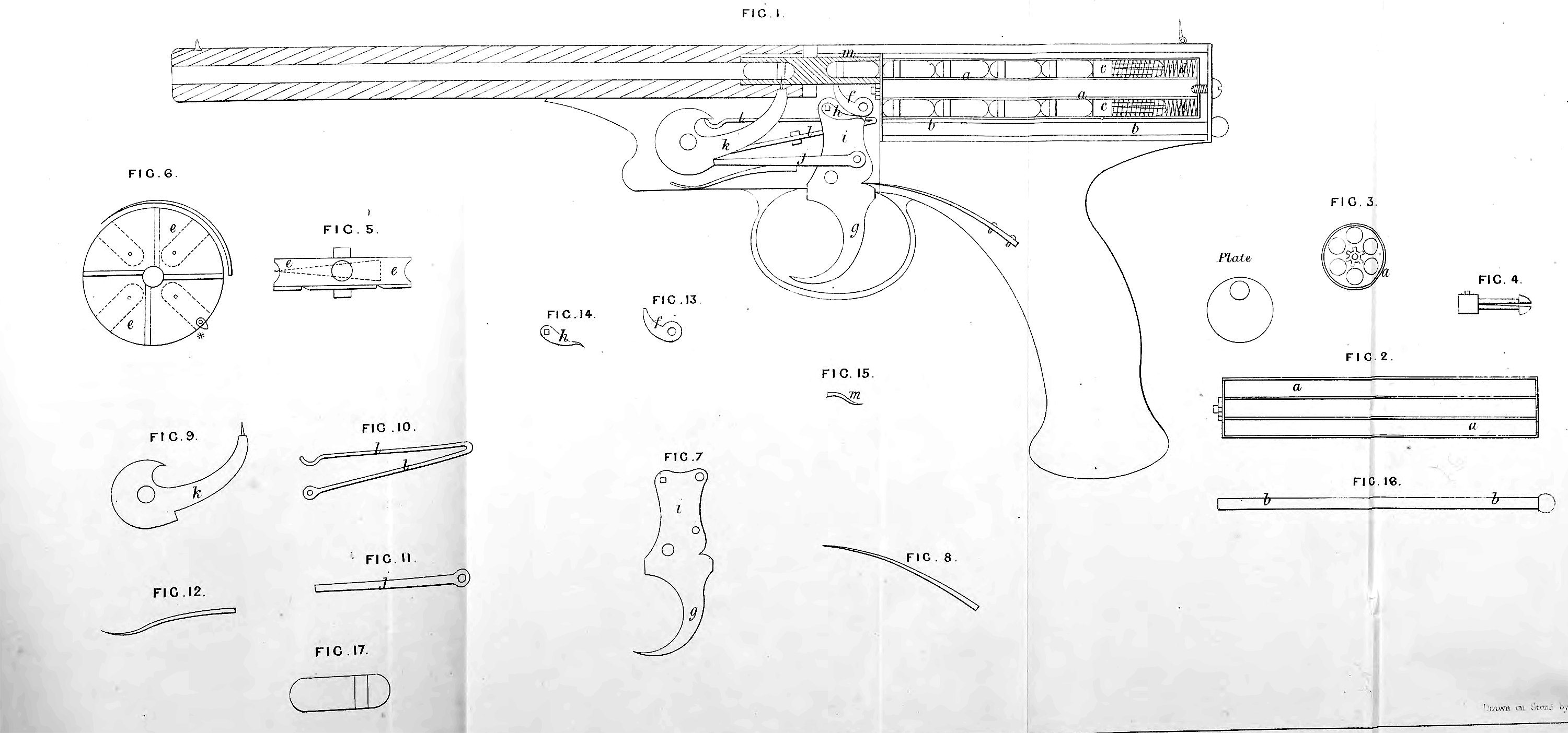
In the Drawing, Figure 1 is a longitudinal section of my improved ‘pistol, shewing all parts that can be seen in such section; Figure 2, longitudinal section of magazine detached; Figure S, end view of magazine; Figure 4, forcer; Figure 5, side view of revolver; Figure 6, plan view of bottom of revolver and spring guard; Figure 7, trigger piece; Figure 8, trigger spring; Figure 9, hammer and needle; Figure 10, main spring for hammer; Figure 11, lifter; Figure 12, spring for lifter; Figure 13, driver; Figure 14, spring for driver; Figure 15, spring for top of revolver; Figure 16, rod for locking forcers while loading; and Figure 17, form of cartridge to be used. Similar letters of reference are placed upon and denote corresponding parts (where such parts appear) at each of the Figures respectively. Upon referring to Figure 1 it will be seen that in order to load the pistol in the first instance the magazine a must be taken out from the breech end of the pistol, the rammer b is then pushed down each chamber so as to drive the ends of the forcers c out of small holes at the end of each chamber; the result being that as the forcers c are opened down the centre, forming a spring*, the moment the ends pass through the holes they expand, and prevent the spiral springs d bringing them forward until required, when by merely pinching the ends of each forcer they will be immediately brought into their places ready for use. The horizontal chamber e, having four chambers in it, now receives a cartridge from the magazine a, the point of the driver / being in a groove at the bottom of the revolver e, and upon drawing back the trigger g the driver f causes the revolver to rotate one quarter of a circle, by which means at every discharge of the fire-arm a fresh cartridge is inserted in the chamber of the revolver immediately behind the one just vacated, the chamber in between having already been supplied, the cartridges being prevented from falling out by the circular spring guard, shewn at Figure 6. Each of the chambers of the magazine is slotted at top to within a short distance of the breech; in these slots pins in each forcer work to prevent the forcers entering the revolver. The driver / is kept up in its place by means of a small spring li, both being attached to the top of the trigger piece i, as shewn; a lifter j is also loosely attached to the trigger piece i by a pin at one end, the other end taking into a notched piece under the hammer k; so it will appear that while the driver / is causing the revolver to rotate one quarter revolution the lifter j is at the same time forcing the hammer k down, and withdrawing the needle from the puncture in the bottom of the revolver; by the time the driver / has effected its purpose the end of the lifter slips over the notched piece at the bottom of the hammer k, when on being disengaged the main spring l forces it upwards; the needle passing through the puncture in the revolver strikes the detonator in the cartridge and causes it to explode. At Figure 6 will be seen a projecting piece * on the under edge of the revolver e. This piece or tooth is here placed to take into a pinion fixed on the end of the magazine a, and having six teeth, the magazine having also six chambers with four cartridges in each chamber, so that when the forcer c has placed the last cartridge of one of the chambers of the magazine a in the revolver e, the piece * takes into one tooth of the pinion and turns the magazine one-sixth of a revolution, presenting the second chamber of the magazine to the action of the revolver, and so on until the whole of the cartridges are discharged. A small spring m is placed above the revolver e to counteract the upward pressure of the driver /. The cartridge I use in my improved fire-arm is prepared as follows:—I make a framework of papier m&che, or other suitable substance that will so far resist the blow of the needle as to ensure the explosion of the detonator which belts this framework, and by explosion communicates with the powder.
Having now described the nature of my improvements in fire-arms, I declare I do not confine myself to the precise details of parts herein shewn or described, or to their relative proportions to each other, so long as no departure is made from the peculiar character of my improvements, and I do not claim any of the mechanical parts herein mentioned taken as parts and not in combination or for the purposes of my Invention.
In witness whereof, I, the said William Henry Dearing Granville, have hereunto set my hand and seal, this Fifteenth day of October, in the year of our Lord One thousand eight hundred and fifty-seven.
W. H. D. GRANVILLE. (l.s.)
Witness,
John Gedge, Patent Agent,
4, Wellington Street South, Strand.